
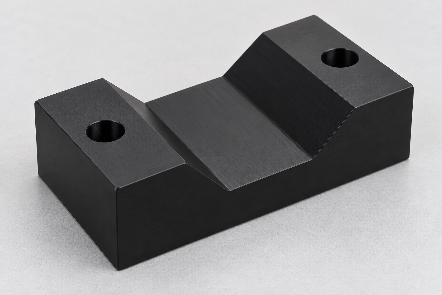
Representative proposed sensor support
This representative example proposes a one-piece black POM-C support for exterior contact with a sealed cylindrical sensor in medical laboratory equipment. The rectangular block has a broad V channel, two sloping contact faces, a relieved root and two plain vertical through holes in its upper shoulders. No sensor, thread, insert or retaining hardware is included in the illustration. No actual customer delivery, manufactured sample or measurement dataset is described. Achieved tolerances, sensor alignment, calibration, electrical properties, damage prevention, validated cleaning, sterile status and medical certification are not presented as actual outcomes of this illustrative CNC route.

Review the sensor and complete mounting arrangement
The proposed order would start with the controlled block drawing and model, housing specification, permitted contact band, mounting base and actual assembly revision. The equipment team would identify sensor variants, cable access, orientation and any separate axial stops or retaining components. A body diameter alone would not determine the interface. The supplier would clarify missing contact and mounting information before choosing a route. Component acceptance, optional seating observations and instrument qualification would remain separate responsibilities, preventing an isolated V-shaped part from being treated as a complete approved sensor mounting or measurement system.
Keep the black POM-C grade traceable
Material records would identify the approved grade, form, condition, lot and purchased final processes. The supplier would not replace it with another black polymer based on visual similarity. Ensinger's general POM machining information would remain processing background, not a medical approval of this component or its sensor contacts. Blank allowance would accommodate the actual holding and finishing plan. Material identity would stay linked through machining and packaging. Electrical, cleaning, wear or biological requirements would need separately agreed evidence for the finished component and real environment instead of assumptions drawn from a generic stock description.
Establish the bottom and mounting references
Initial operations would create the accepted bottom support reference and other surfaces needed to relate the V channel and shoulder holes. Holding would protect future useful contacts and avoid forcing the block into a favorable but misleading shape. Chips would be removed before reorientation. The supplier would review reference transfer rather than reset each feature from a convenient raw edge. Final acceptance would follow the specified delivered condition after relevant processes. A support that looked correctly aligned only when strongly clamped would not automatically conform to the drawing or establish the sensor's actual position in the instrument.
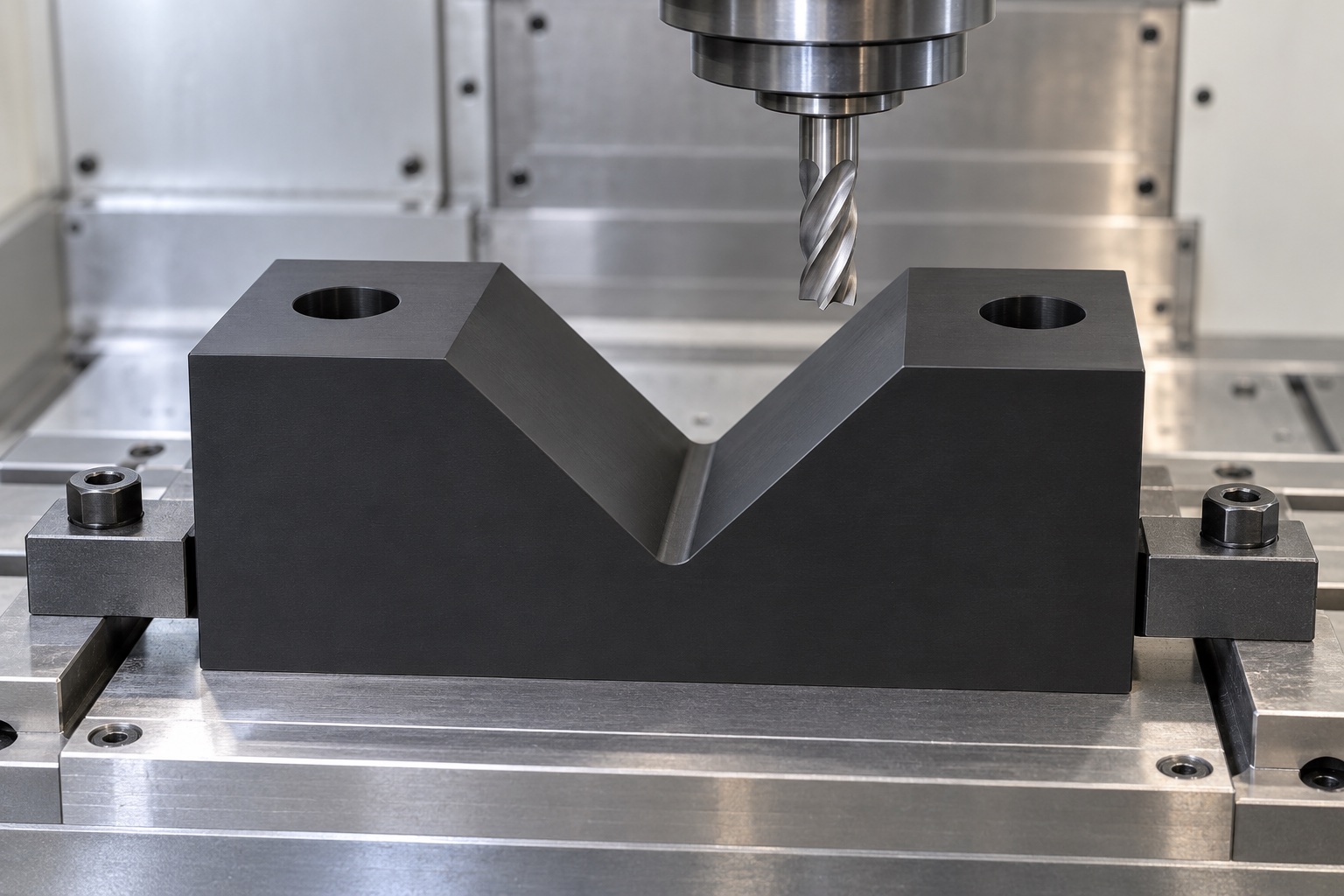
Machine the approved V faces and root
The V angle, useful contact length, position and root relief would follow the controlled geometry. Tool access and the remaining section below the channel would be reviewed before finishing. The supplier would not choose an arbitrary cutter profile or deepen the root merely to fit an unidentified housing. The model and drawing would be reconciled before the final operation. The two sloping contacts and root would retain distinct functions. Authorized changes would appear in revised geometry and inspection documents so the next order would not depend on a hand-sanded sample or an assumed universal sensor center height.
Create the two plain mounting holes
The holes would follow released size, position and edge requirements and remain distinct from precision locating bores, threads or insert seats. The actual fastening arrangement would be reviewed without selecting bolts from the image. If the equipment required additional locating, axial stop or retaining features, they would need their own approved definitions. The supplier would not add a recess or another hole to resolve an unexpected assembly observation. Required relationships between the holes, bottom face and V contacts would remain part of dimensional inspection rather than being inferred from a block bolted to a convenient base.
Finish and clean the useful contact boundaries
The supplier would inspect channel entries, sloping faces, root transitions, hole exits and outer corners for attached material or unwanted sharp features. Approved edge breaks would preserve useful contact lengths and clearances. Sanding to improve one sensor fit would require an authorized geometry review rather than disappear as cosmetic finishing. Cleaning and final processing would follow the purchased scope. A smooth black surface would not prove measured particles, electrical isolation, absence of shell damage or validated disinfection. Grade, lot, revision and adjustments would remain linked to the actual component before dimensional acceptance and mechanical packing.
Inspect the support geometry and its relationships
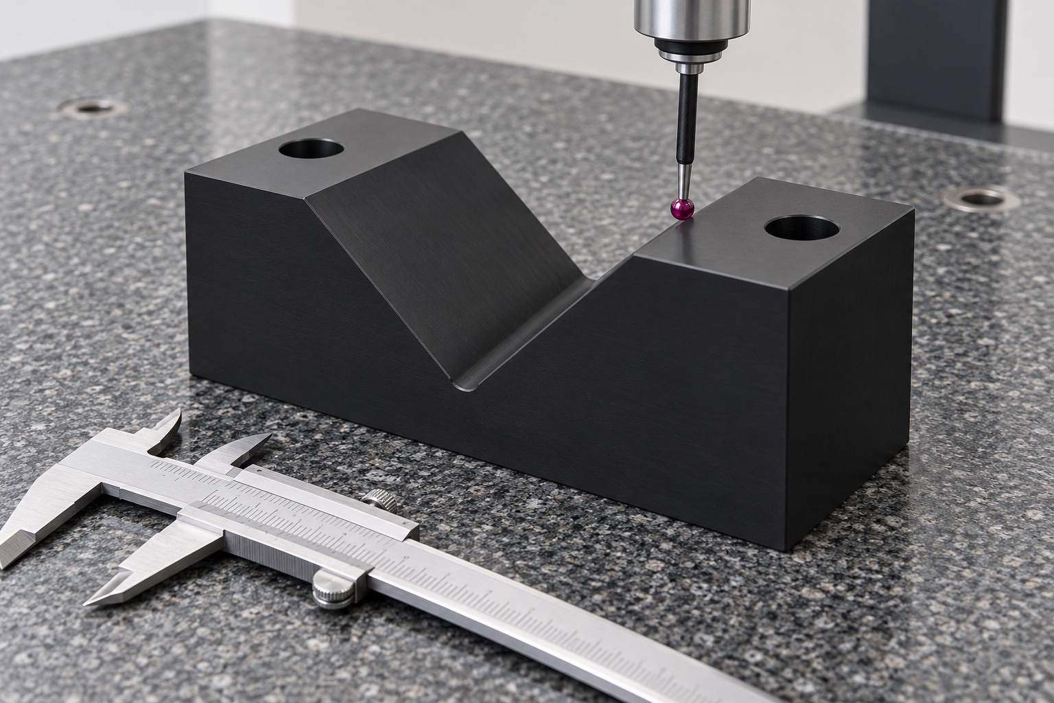
The proposed plan would assign methods to the V faces, angle, root, base reference, mounting pattern and specified positional relationships. Support and measurement contacts would avoid distorting the polymer or concealing a mismatch. A caliper checking outside width or a cylinder resting in the groove would not verify the whole block. Inaccessible regions would be addressed before acceptance. An illustrative CMM setup would not be reported as an achieved tolerance. Real observations would refer to the finished component, revision and agreed condition, not an unidentified sensor or a fixture-constrained appearance used as a substitute for geometric requirements.
Prepare records without fictional sensor results
The proposed first-article record would identify revision, material lot, numbered features, methods and final condition. No measured values are supplied because this representative example has no manufactured specimen or actual inspection record. A real project would retain discrepancies and authorized changes transparently. Component conformity would not establish sensor calibration, measurement accuracy, retention or instrument safety. Optional assembly observation and complete-device evaluation would remain separate deliverables. This prevents an illustrative manufacturing route from becoming an invented customer acceptance, a claimed positioning improvement or a qualified medical sensor performance result that has not actually been demonstrated.
Limit optional observations with the actual housing
An agreed trial could examine entry, intended exterior contacts, seating, cable clearance and access using identified block, sensor, base and hardware revisions. Orientation and the separate retaining arrangement would be recorded. Unexpected contact with labels, joints or connectors would be reviewed before modifying the block or substituting another sensor. Favorable static seating would not qualify axial position, angular retention, vibration behavior or measurement performance. Trial pieces would remain separate from accepted production. Approved adjustments would enter revised documents before another order rather than become an informal fitting reference for other sensors or equipment assemblies.
Protect the contact faces and distinguish variants
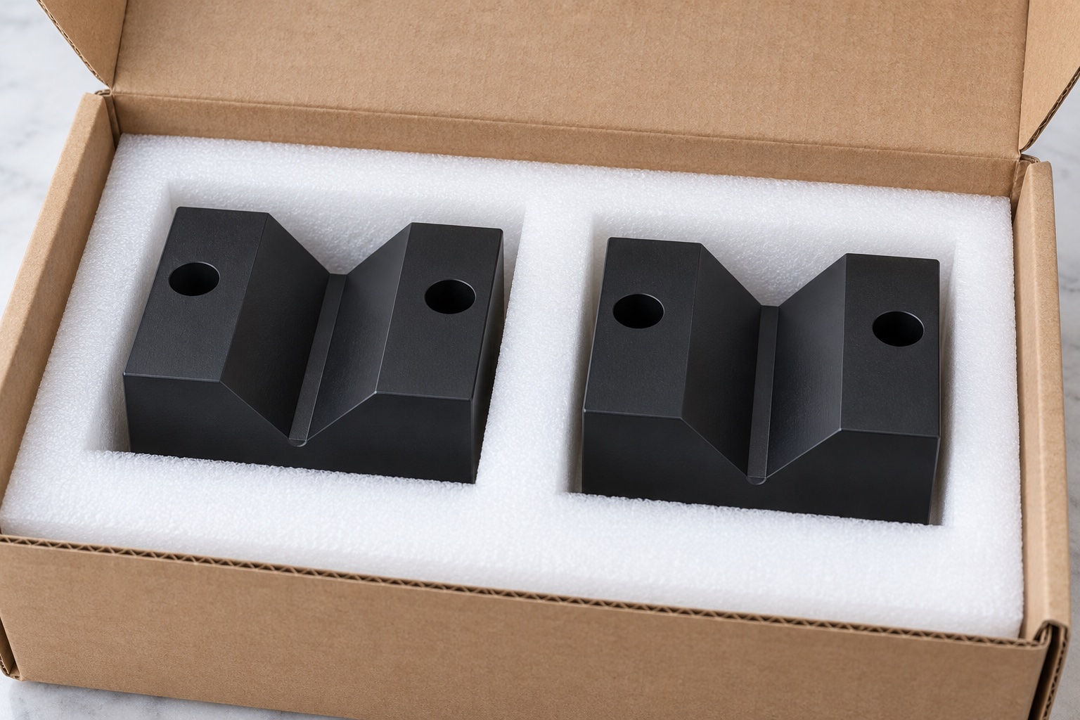
Finished blocks would occupy separate pockets or sleeves sized to protect V faces, roots and mounting references without deformation. Loose metal hardware would not strike or embed into useful contacts. Mechanical transport protection would not imply sterile supply or validated cleaning. Grade, lot, revision, final process and inspection status would accompany the shipment. Receiving checks would distinguish visually similar blocks with different V angles, contact lengths, root clearances or hole positions before installation. The instrument team would retain responsibility for its separately defined sensor alignment, calibration, retaining and service evaluations under actual application conditions.
Maintain a sensor-specific production baseline
The final package would preserve released geometry, permitted housing contact, sensor variants, bottom and mounting references, retaining arrangement, material evidence, final condition, inspection and packing. Approved prototype changes would become controlled revisions before repeated manufacture. Housing, connector, label, base or cleaning changes would trigger review even if the block outline appeared unchanged. This representative workflow defines a traceable CNC polymer project without inventing customer history, achieved tolerances or calibration results, and without confusing a dimensionally accepted support with a universally qualified medical sensor mounting, electrical isolation or validated measurement system.
Manufacturer background reference: www.ensingerplastics.com.
FAQ
Is this an actual customer-delivered sensor support?
No. It is a representative proposed machining workflow with illustrative images. No delivered order, manufactured specimen or measured sensor result is described. A real project needs approved documents, grade and production evidence, actual dimensional records and any separately required application evaluations.
Is a sensor or retaining assembly included?
No. The illustration concerns the isolated POM-C block. Sensor housing, base, fasteners, axial stops and retaining hardware belong to the separately identified assembly documents. Their function and qualification cannot be inferred from a V groove or two mounting holes.
Does the example demonstrate sensor alignment accuracy?
No. Neither an actual instrument test nor a measured sensor alignment result exists here. Component dimensions and favorable static seating do not establish calibration, measurement accuracy, vibration behavior or retention. The complete actual instrument needs separately defined evaluation and evidence.
Can the V faces be sanded to match one housing?
Not as an undocumented substitute for approved geometry. Angle, useful contact, root clearance and height relationships require controlled definition. Any change needs authorization, revised documents and relevant inspection rather than a hand-sanded block becoming the next production master.
Does the black surface prove cleaning or electrical performance?
No. A clean-looking component and mechanical protective packaging do not demonstrate electrical insulation, validated cleaning, disinfectant compatibility or sterile status. The exact grade, finished geometry and real environment require their own agreed requirements and supporting evidence when such properties are needed.
What would another order review?
Review the exact sensor housing, contact band, labels, connectors, V geometry, root, mounting base, retention, polymer grade and final process. Incorporate authorized changes into controlled revisions, not a manually altered prototype or another instrument's calibration and performance assumptions.

tanghangyun@oemach.com