
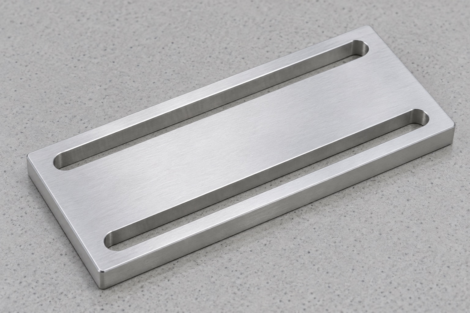
Representative proposed adjustment plate
This representative example describes a proposed one-piece 6061 aluminum adjustment plate for a service module in medical laboratory equipment. The flat rectangular plate has two parallel elongated through slots with rounded closed ends, broad opposing faces and no additional holes or threads. No actual customer delivery, manufactured specimen or measurement record is described. The illustrations do not establish achieved tolerances, adjustment travel, retention, load capacity, cleaning validation, sterile status, medical certification or equipment safety. The proposed workflow concerns custom component manufacture; the complete adjustment and holding arrangement would require its own approved design and application evidence.

Review the mounting assembly before production
The proposed order would begin with the controlled model and drawing, mating support, module interface, fastener arrangement and actual revision. The equipment team would identify useful contacts, permissible settings and the complete movement envelope. A slot's nominal length would not automatically become the assembly travel requirement. The supplier would clarify missing hardware clearances or support conditions before selecting operations. Manufacturing acceptance, optional fitting and full application qualification would remain separate deliverables. A convenient photo or one mounting sample would not silently define the geometry or authorize substitution of a washer, fastener or stop feature.
Preserve the approved material package
Material records would identify the accepted 6061 grade, stock condition, form, lot and purchased final treatment. Blank allowance would follow the actual holding and finishing plan rather than a universal plate thickness. Identity would remain traceable through slot machining, reorientation and dispatch. A silver appearance would not authorize a different alloy or treatment. Material evidence would identify the stock within its scope, not prove holding performance, validated cleaning or sterile supply. Any relevant surface, residue or environmental requirement would need a separately agreed definition and evidence tied to the actual finished component and application.
Establish face references before slot finishing
Initial operations would create the useful face and thickness references required by the drawing. The supplier would review support near the future slots and avoid accepting a component only because strong clamping made it appear flat. Chips would be removed before reference transfer. General workholding principles would guide planning without becoming a validated recipe for this particular fixture. Purchased processes affecting thickness, contacts or openings would remain visible in the route. Final acceptance would address the agreed finished condition, not a raw blank, a distorted clamped plate or an unidentified mounting sample used as a replacement for specified references.
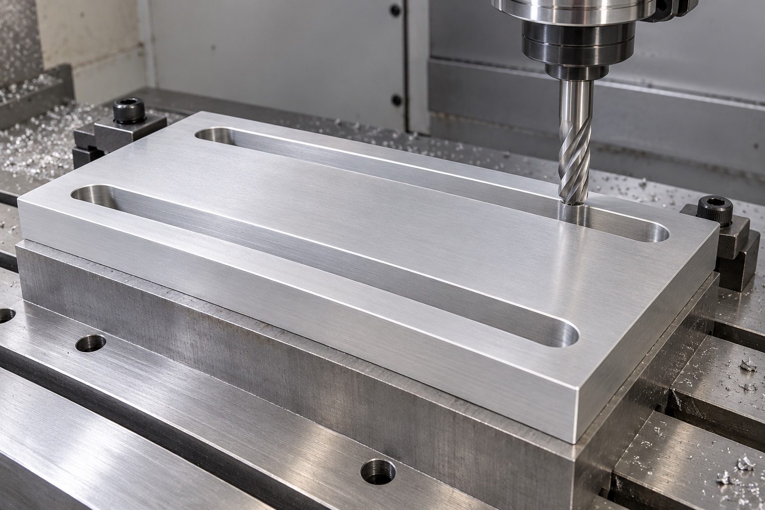
Machine two controlled closed-ended slots
Each slot would follow the approved width, end geometry, straight portions and position within the plate. The supplier would review cutter access and the remaining material around both openings before finishing. It would not extend a slot, remove an enclosing end or enlarge a wall merely to obtain a favorable hand fit. Conflicts between drawing and model would be resolved before the final cut. Authorized changes would enter controlled documents and the inspection plan. This preserves the distinction between a released adjustment pattern and an informal opening modified for one particular module, support or fastener sample.
Keep the pattern related to the mounting faces
The two slots would be inspected in relation to accepted face references and the required spacing and orientation. Their role would remain explicit: clearance and adjustment should not automatically be treated as precision location. If the equipment design needed separate locating, stop or retaining components, those would have their own controlled definitions. The supplier would not add a hidden dowel, recess or extra hole to complete an ambiguous mounting scheme. A plate bolted to a support would not by itself demonstrate the full relationship between the device module, adjustment range and equipment coordinate system.
Finish edges without changing useful geometry
The supplier would inspect slot entrances, end transitions, through exits and external corners for attached material or unintended sharp features. Approved edge breaks would preserve useful faces and the defined movement envelope. Polishing would not conceal an incorrectly positioned or oversized opening. Cleaning and final treatment would follow the purchased scope with relevant finished-state checks. Smooth aluminum would not prove measured particles, antimicrobial behavior, validated disinfection or sterile delivery. Lot, revision and authorized adjustments would remain associated with the actual plate before dimensional acceptance and mechanical protective packaging.
Inspect related features in the agreed final state
The proposed plan would assign methods to thickness, useful faces, slot profiles, widths, spacing, positions and required geometric relationships. Support, contact access and reference establishment would be agreed. One pin or an outside-size caliper reading would not verify the complete pattern. Inaccessible features would be addressed before acceptance. A CMM illustration would show a possible inspection setup, not an achieved tolerance. Actual observations in a real project would refer to the finished plate after relevant processing, not to its fixture-constrained appearance or the fact that one unidentified module could be bolted onto it.
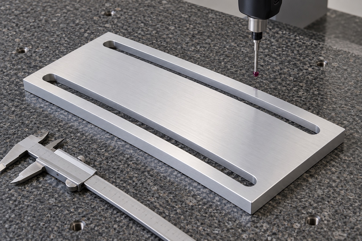
Build first-article records without invented values
The proposed report would identify drawing revision, material lot, numbered features, methods and final condition. No numerical measurements are supplied because this example contains no manufactured sample or actual inspection dataset. A real order would retain discrepancies and approved changes transparently. Dimensional conformity would not establish load capacity, preload, positional stability or safe service adjustment of the complete device. Component inspection, optional assembly observation and application qualification would remain separately identified. This prevents a plausible machining route from being reported as a customer's acceptance, a measured improvement or an achieved medical equipment production result.
Limit any optional adjustment observation
An agreed trial could examine insertion, seating, access and intended movement using identified plate, module, support and hardware revisions. The actual installation method and holding arrangement would be documented. Unexpected rocking or interference would be reviewed before altering the plate or substituting fasteners. Favorable hand adjustment would not qualify vibration behavior, load, preload or stability during operation. Trial pieces would remain separate from accepted production. Approved changes would enter revised documents before another order, rather than leaving a manually extended slot as the informal reference for different modules, hardware envelopes or maintenance procedures.
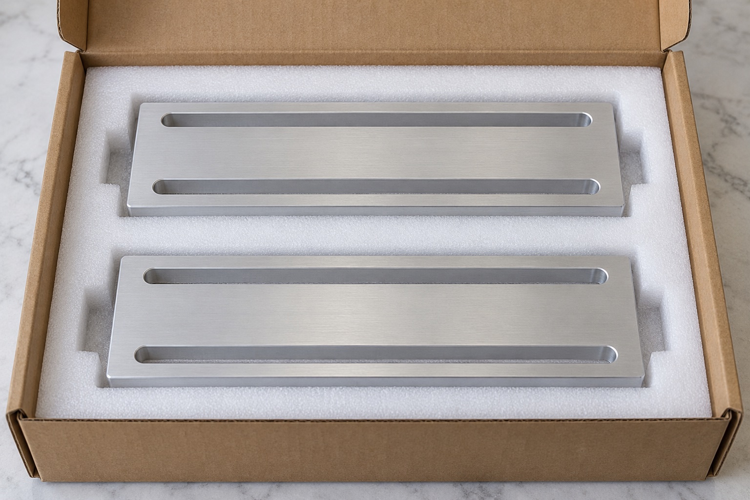
Pack the accepted geometry without distortion
Finished plates would occupy separate pockets or supports that protect broad contacts and slot edges. Packaging restraints would avoid bending the plate or pressing loose hardware into useful faces. Mechanical transport protection would not imply sterile supply or validated cleaning. Lot, revision, final treatment and inspection status would accompany the shipment. Receiving checks would distinguish visually similar plates with changed thickness, slot width, length or spacing before installation. These measures would preserve the supplied component and its traceable identity while leaving the complete medical instrument's holding, alignment and service evaluations to separately defined application work.
Keep an adjustment-specific production baseline
The production package would preserve released geometry, mating interfaces, hardware, approved settings, motion envelope, contacts, material evidence, final processes, inspection methods and packing scope. Authorized prototype adjustments would become revised documents before repeated manufacture. Changes to supports, modules or treatments would trigger review even when the outside outline appeared unchanged. This representative workflow defines a traceable CNC supply project without inventing customer history, achieved tolerances or retention ratings, and without confusing a dimensionally accepted slotted plate with a qualified complete medical equipment adjustment, positioning or service-safety system.
Manufacturer background reference: www.carrlane.com.
FAQ
Is this a real customer-delivered adjustment plate?
No. It is a representative proposed CNC workflow with illustrative images, not a report of a delivered order or manufactured sample. A real project requires its own approved documents, material evidence, production records and actual finished-component inspection results.
Does the example provide a measured travel range?
No. Neither a manufactured component nor an assembled trial is available here. The real equipment team must define the permissible settings, hardware envelope and support conditions. Nominal slot length alone does not establish the complete assembly's usable adjustment travel.
Are the fasteners and holding method included?
The illustration shows only the plate. Actual fasteners, washers, stops and any additional locating or holding components belong to the separately controlled assembly definition. Their selection and performance cannot be inferred from the two elongated slots or a smooth contact face.
Do the inspection images prove a tolerance?
No. They illustrate possible tools and arrangements. A real report needs identified characteristics, references, methods and actual measurements of the finished component. A photograph and an apparently favorable fit do not demonstrate an achieved tolerance or complete-device stability.
Can a local slot extension be kept for future orders?
Only as an authorized change incorporated into revised geometry and inspection requirements. A hand-modified trial plate should not become an undocumented production master. Review the full adjustment envelope and surrounding equipment before approving a change to either closed slot.
What should another order review?
Review the module, support and hardware revisions, permitted settings, slot pattern, useful contacts, thickness, grade and final treatment. Retain approved changes in controlled documents and actual reports, not in a manually altered sample or performance assumptions from another installation.

tanghangyun@oemach.com