
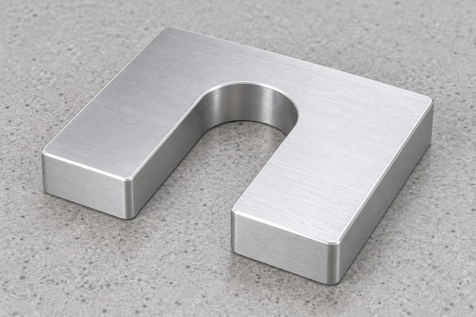
Representative proposed open-sided spacer
This representative example describes a proposed one-piece 6061 aluminum horseshoe spacer plate for a service-module mounting stack in medical laboratory equipment. Its rectangular outline has one deep open-ended U slot, parallel walls, rounded root and opposing flat contact faces. No holes, threads or separate fasteners are part of the illustrated plate. No actual customer delivery or manufactured sample is described. Achieved tolerances, load capacity, preload, retention, vibration resistance, sterile status, medical certification and validated equipment safety are not presented as actual measured results of this illustrative CNC manufacturing workflow.

Review the actual stack before selecting a route
The proposed order would start with the released plate model and drawing, both mating surfaces, actual stem, retention hardware and installation revision. Useful contacts and the complete insertion path would be identified, not inferred from one photograph or nominal gap. The supplier would clarify missing geometry before machining. The equipment team would define retention and permitted service actions separately. Similarity to a catalog spacer would not transfer another component's rating. The manufacturing scope would distinguish dimensional acceptance, optional fitting and application qualification so that an open slot was not silently treated as a locking mechanism.
Preserve the approved material package
Material records would identify the accepted 6061 condition, stock form, lot and purchased final processing. The blank allowance would suit planned holding and finishing rather than a universal stock thickness. Traceability would remain with the component when the U slot was opened and the plate reoriented. A silver appearance would not justify another alloy or unapproved treatment. Stock evidence would identify supplied material within its scope, not prove load, cleanliness or sterile status. Any application-specific surface or environmental requirement would need its own agreed definition and acceptance evidence from a real manufacturing order.
Establish contact references with adequate support
Initial operations would establish suitable references for the opposing faces and subsequent opening profile. Holding contacts would protect useful surfaces and account for the remaining open sections. The supplier would remove chips before reorientation and avoid accepting the plate solely because fixture force made it appear flat. General workholding guidance would be background, not a validated fixture recipe. The final inspection condition would be agreed before manufacture. A raw holding edge or convenient stock face would not silently replace the approved functional references linking thickness, slot and useful contacts in the actual service-module stack.
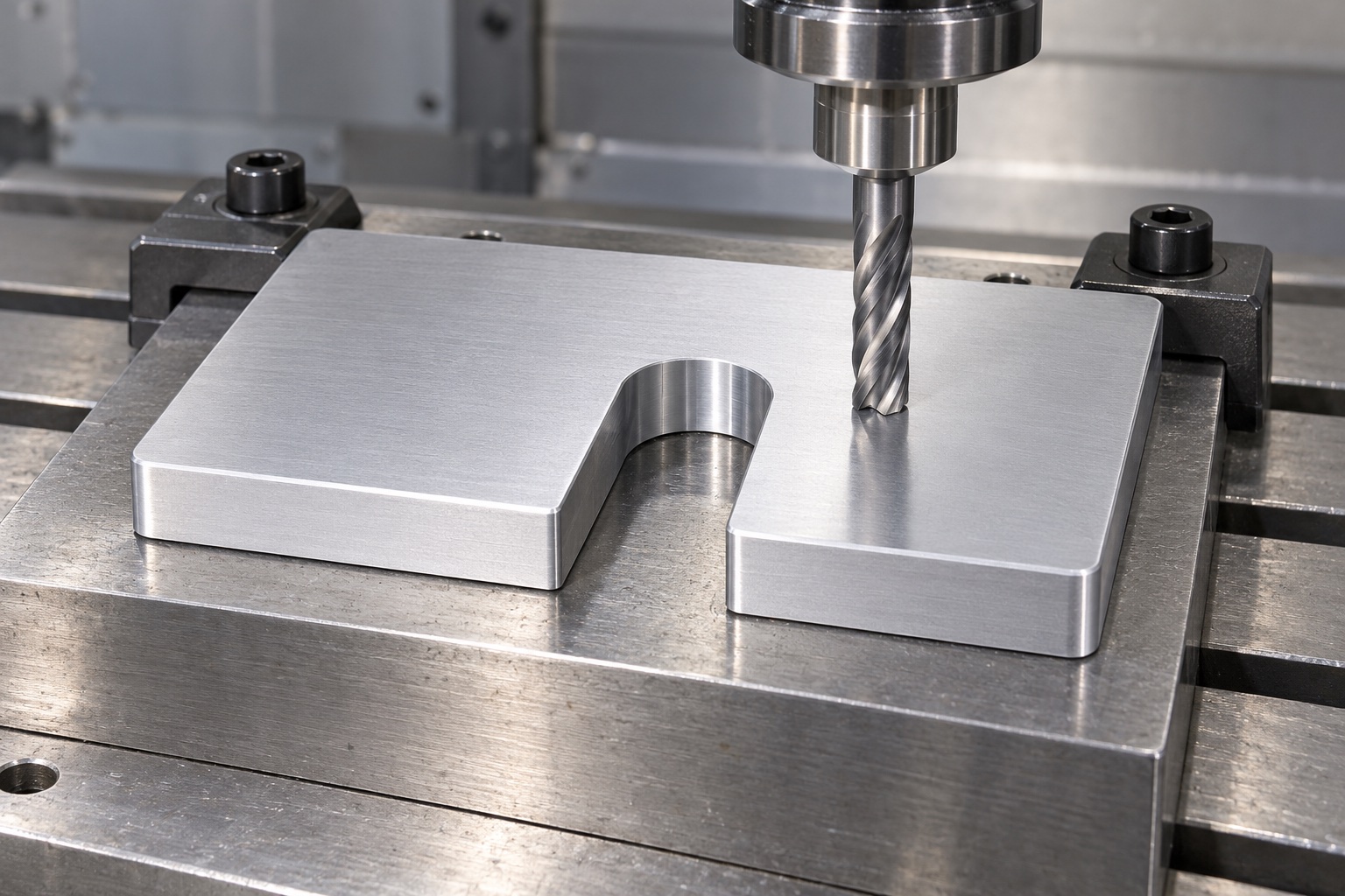
Machine the specified U-shaped slot
Slot width, position, depth within the plate outline, parallel sides and rounded root would follow released geometry. The slot would pass through the thickness and open at the specified edge. The supplier would review tool access and remaining arm and bridge sections before finishing. It would not widen the opening or shorten a side merely to pass an unidentified stem. Model and drawing conflicts would be resolved before the final cut. Authorized changes would enter controlled documents, preserving the distinction between a specific mounting concept and an assumed universal insertion or maintenance procedure.
Retain the finished axial contact definition
Useful upper and lower faces, final thickness and required relationships would follow the approved stack. Permitted edge breaks and noncontact areas would be distinguished from seating regions. Purchased treatments affecting these features would be included in relevant final checks. The supplier would not locally thin an arm to fit one sample or introduce an informal shim layer. Any such proposal would require authorization and revised inspection requirements. Component conformity would not establish preload, stiffness, retention or safe service removal of the complete module, stem, support and hardware arrangement used by the equipment team.
Finish slot roots and arm ends carefully
The supplier would examine open entries, root transitions, arm tips and exterior corners for attached material or unwanted sharp features. Approved edge requirements would preserve useful contact and the released path. Polishing would not conceal an incorrectly positioned opening or replace a geometry decision. Cleaning and final processing would follow the purchased scope with relevant finished-state checks. Smooth aluminum would not demonstrate measured particles, antimicrobial action, validated cleaning or sterile supply. Material lot, revision and any authorized adjustment would remain linked to the actual component before dimensional inspection and mechanical protective packaging.
Inspect related features in the agreed state
The proposed plan would identify methods for thickness, useful faces, slot profile and location, outside geometry and required relationships. Support, contact access and reference establishment would be explicit. Outside caliper measurements alone would not verify every controlled characteristic. Inaccessible regions would be addressed before acceptance. A CMM or micrometer picture would illustrate a possible method, not an achieved tolerance. Actual observations on a real project would refer to the finished plate after relevant machining and purchased processes, rather than a heavily constrained part or an unidentified assembly sample used as a substitute for the dimensional drawing.
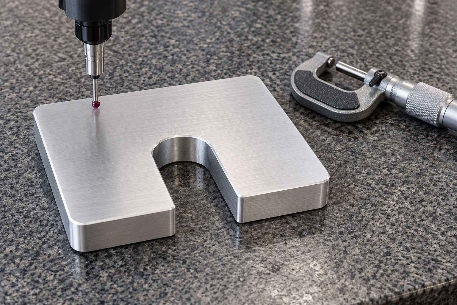
Prepare first-part records without invented values
The proposed report would identify drawing revision, material lot, numbered characteristics, methods and final condition. No numerical values are supplied because no manufactured sample or actual measurement record exists in this representative example. A real order would retain discrepancies and authorized changes transparently. A conforming dimensional report would not establish module load capacity, retention, preload stability or medical equipment safety. Component inspection, optional fit observations and complete application qualification would remain separate deliverables. The workflow therefore does not claim a customer acceptance, successful production result or performance improvement that has not actually been demonstrated.
Bound an optional installation observation
An agreed trial could examine side entry, seating, stem clearance and access using identified plate, module, support and hardware revisions. The actual installation method and any approved retention component would be recorded. Unexpected rocking or interference would be reviewed before modifying the plate or mating pieces. Successful hand fitting would not qualify vibration behavior, load, preload or removal under service conditions. Trial pieces would remain distinct from accepted production. Approved changes would enter revised documents rather than let a hand-filed slot become the informal reference for other stems, stack heights or medical equipment service arrangements.
Package without loading the open arms
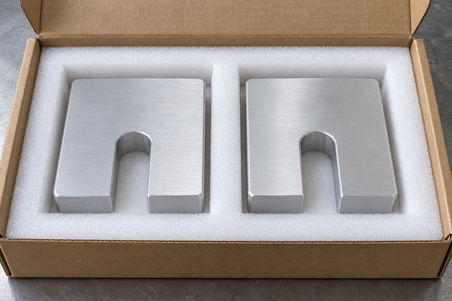
Finished plates would be separated in adequately sized supports that protect contact faces, slot edges and arm ends. Restraint would avoid bending the U section or pressing loose fasteners onto accepted surfaces. Mechanical transit protection would not imply sterile delivery. Lot, revision, final treatment and inspection status would accompany the shipment. Receiving checks would distinguish similar plates with changed thickness, root radius or slot width before installation. These measures would preserve the accepted component's identity while leaving retention, environmental and maintenance qualification of the actual assembled medical laboratory module to separately defined application evaluation.
Maintain a stack-specific production baseline
The production package would preserve released geometry, mating surfaces, stem and retention arrangement, insertion path, useful contact areas, material evidence, final processing, inspection methods and packing scope. Approved prototype adjustments would become revised documents before repeat manufacture. A changed support, stem, module or treatment would trigger review even when the outside outline looked similar. This representative workflow outlines a traceable custom CNC project without inventing customer history, achieved tolerances or retention ratings, and without confusing a dimensionally conforming spacer plate with a qualified complete medical equipment locking, support or service-removal system.
Manufacturer background reference: www.carrlane.com.
FAQ
Is this an actual delivered customer spacer?
No. It is a representative proposed manufacturing workflow with illustrative images. There is no customer delivery, manufactured specimen or measured result. A real order would require its own approved documents, material records, production evidence and actual inspection report.
Is retention included in the plate itself?
No independent locking feature is defined. The actual mounting stack must identify its retention method. The open U slot is geometry, not a demonstrated locking or vibration-resistance result. Relevant application requirements and verification would be agreed separately.
Does this case include load or preload results?
No. No manufactured sample or assembly test record is available. Dimensional acceptance and favorable hand fitting would not establish load capacity, stiffness, preload stability or safe service removal of the complete actual mounting arrangement.
Can a supplier locally reduce thickness to fit?
Only through an authorized change reflected in controlled documents. Useful contacts, thickness and final processing are part of the released stack. An informal local adjustment should not replace the drawing or become a hidden reference for subsequent production.
Do the inspection images prove a tolerance?
No. They illustrate possible checking tools and arrangements. A real report needs identified characteristics, methods, references and observations from the actual finished component. An image is not measured evidence of dimensional capability or complete application qualification.
What would a repeat order review?
Review module and support revisions, stem, retention hardware, insertion path, thickness, contact faces, material and treatment. Approved changes must enter the production baseline rather than remain in a manually modified sample or a transferred performance claim from another equipment installation.

tanghangyun@oemach.com