
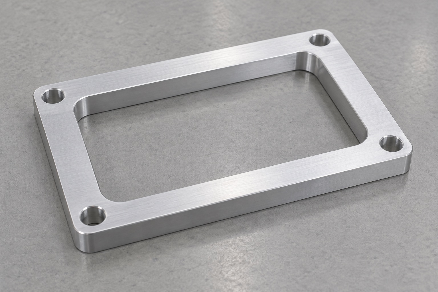
Representative proposed detector adapter frame
This representative example describes a proposed one-piece 6061 aluminum frame between a medical laboratory detector housing and an equipment mounting structure. The rectangular ring has one rounded rectangular through opening, four plain corner mounting holes, flat contact lands and uniform nominal thickness. It has no glass, optics, electronics, threads or gasket in the concept. No actual customer delivery or manufactured sample is described. Achieved tolerances, detector accuracy, shielding results, vibration performance, sterile status, medical certification and validated equipment safety are not presented as actual measured production outcomes of this illustrative manufacturing workflow.

Review the detector housing and equipment support
The proposed order would begin with controlled documents for the frame, detector housing, equipment support and actual mounting hardware. Useful contact areas, opening envelope, installation direction and any separate locating method would be identified before selecting a route. Incomplete interfaces would be clarified rather than copied from a photograph. The supplier would distinguish mounting clearance from precision registration. A frame with the correct outside dimensions would not automatically be compatible with every detector version. Any requirement for adjustment, shimming or separate retention would belong to the released assembly instead of an undocumented machining assumption.
Preserve the specified aluminum identity
The material package would identify the approved 6061 condition, stock form, lot records and purchased final processing. Blank allowance would be chosen for the planned holding and finishing sequence, without claiming a universal stock thickness. The supplier would retain material identity through the large opening operation, reorientation and shipment. Similar silver appearance would not justify another alloy or an unapproved finish. The material evidence would identify stock within its scope, not establish detector calibration or electromagnetic behavior. Application-specific cleaning, contact or safety requirements would need their own approved definitions and acceptance evidence.
Establish references before opening the ring
Initial operations would establish suitable faces and locating references for the outside, opening and mounting pattern. Holding would support the remaining material without accepting a frame solely because clamping forced it into a favorable shape. Fixture contacts would avoid damage to useful lands. The supplier would review how references transfer when the part is turned over, remove chips from contacts and retain enough allowance for agreed finishing. Carr Lane's general workholding principles would be background only, not a validated fixture recipe. Final acceptance would address the released finished frame rather than only its restrained machining condition.
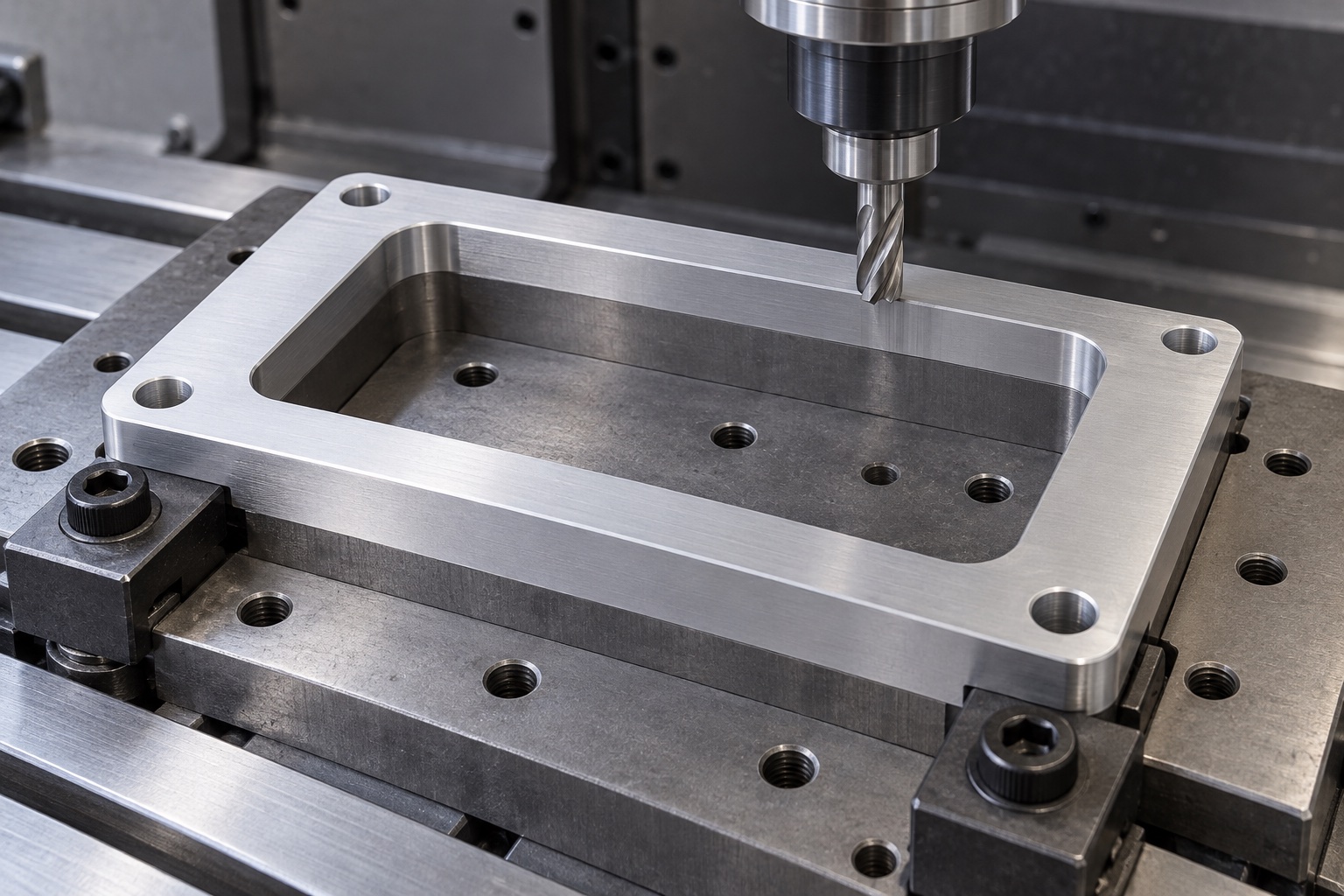
Machine the controlled internal opening
The rounded rectangular through opening would follow approved profile, corner radii and location relative to the functional references. Tool access and the remaining frame width would be reviewed before production. The supplier would not enlarge corners or thin one side to make an unidentified detector housing pass. Model and drawing conflicts would be resolved before cutting the final boundary. Accepted changes would enter controlled documents. The open center would remain a mechanical feature; its appearance would not establish an optical aperture, light suppression, imaging quality or the detector assembly's calibration under the actual instrument operating conditions.
Produce the four plain mounting holes
Each through hole would follow its approved size, position and edge requirements. The concept would not acquire counterbores, countersinks or threads merely because a convenient fastener was available. The supplier would check actual tool access and relationships to the frame opening and contact lands. A favorable pin entry at one corner would not verify the full pattern or face geometry. If the equipment team introduced dowels or another locating method, that would trigger a documented design and inspection review rather than a silent reclassification of the four existing clearance holes as precision location features.
Finish lands and edges in the purchased condition
Finishing would examine internal corners, hole entries and outer boundaries for attached material or unwanted sharp features. Released edge breaks would preserve useful land area, remaining wall and installation clearance. Cleaning and final surface processing would follow the order with relevant finished-state dimensional checks. Polishing a contact face to fit one sample would require authorization rather than disappear into cosmetic work. A bright finish would not demonstrate antimicrobial action, quantified particles, validated cleaning or sterile delivery. The final component would remain linked to its drawing revision, material evidence and actual purchased treatment before inspection and packing.
Inspect the related frame characteristics
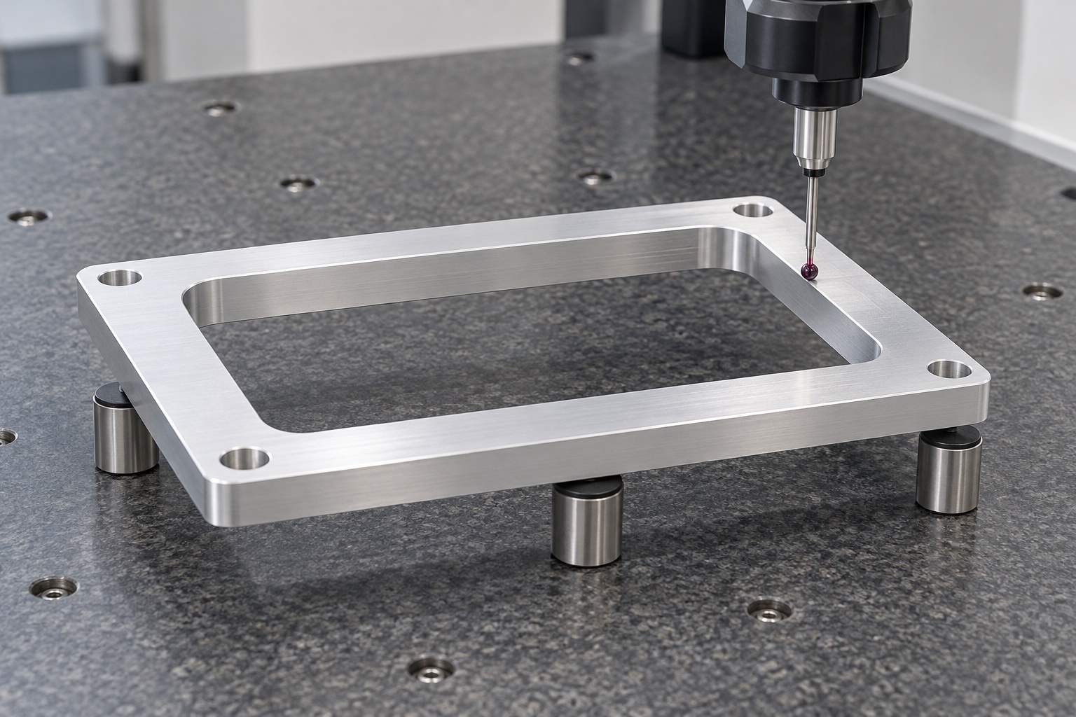
The proposed inspection plan would map opening profile and position, hole pattern, thickness, useful faces and required geometric relationships to agreed methods. Support and reference establishment would be explicit. Selected caliper measurements would not substitute for every controlled characteristic. Inaccessible corners or face areas would be discussed before inspection. The frame would not be accepted exclusively in a fixture-distorted condition. A CMM image would illustrate a possible checking arrangement, not an achieved result. Final observations would refer to the actual component after relevant operations and any purchased treatment that could influence its mating interfaces.
Create first-part records without numerical fiction
The proposed report would identify numbered drawing characteristics, revision, material lot, methods and final condition. No measured values are supplied because this example contains no manufactured sample or actual inspection record. Nonconformance and authorized changes would remain traceable on a real project. A conforming frame report would not establish detector calibration, optical alignment, shielding or complete instrument safety. Component inspection, optional assembly observations and application qualification would remain separate deliverables. This avoids turning an illustrative manufacturing sequence into unsupported evidence of customer acceptance, performance improvement or a production capability result that has not actually been demonstrated.
Limit an optional mechanical assembly observation
An agreed trial could examine seating, opening clearance, screw access and cable exit with identified frame, detector housing, support and fastener revisions. The installation method and approved locating or shimming elements would be recorded. Unexpected rocking or interference would be reviewed before altering either mating part. Successful hand assembly would not qualify vibration life, alignment stability, electromagnetic behavior or diagnostic performance. Trial frames would remain distinguishable from accepted production. Approved prototype adjustments would enter revised documents instead of allowing a filed corner or informal spacer to become the reference for a later detector variant.
Pack the frame without loading its open section
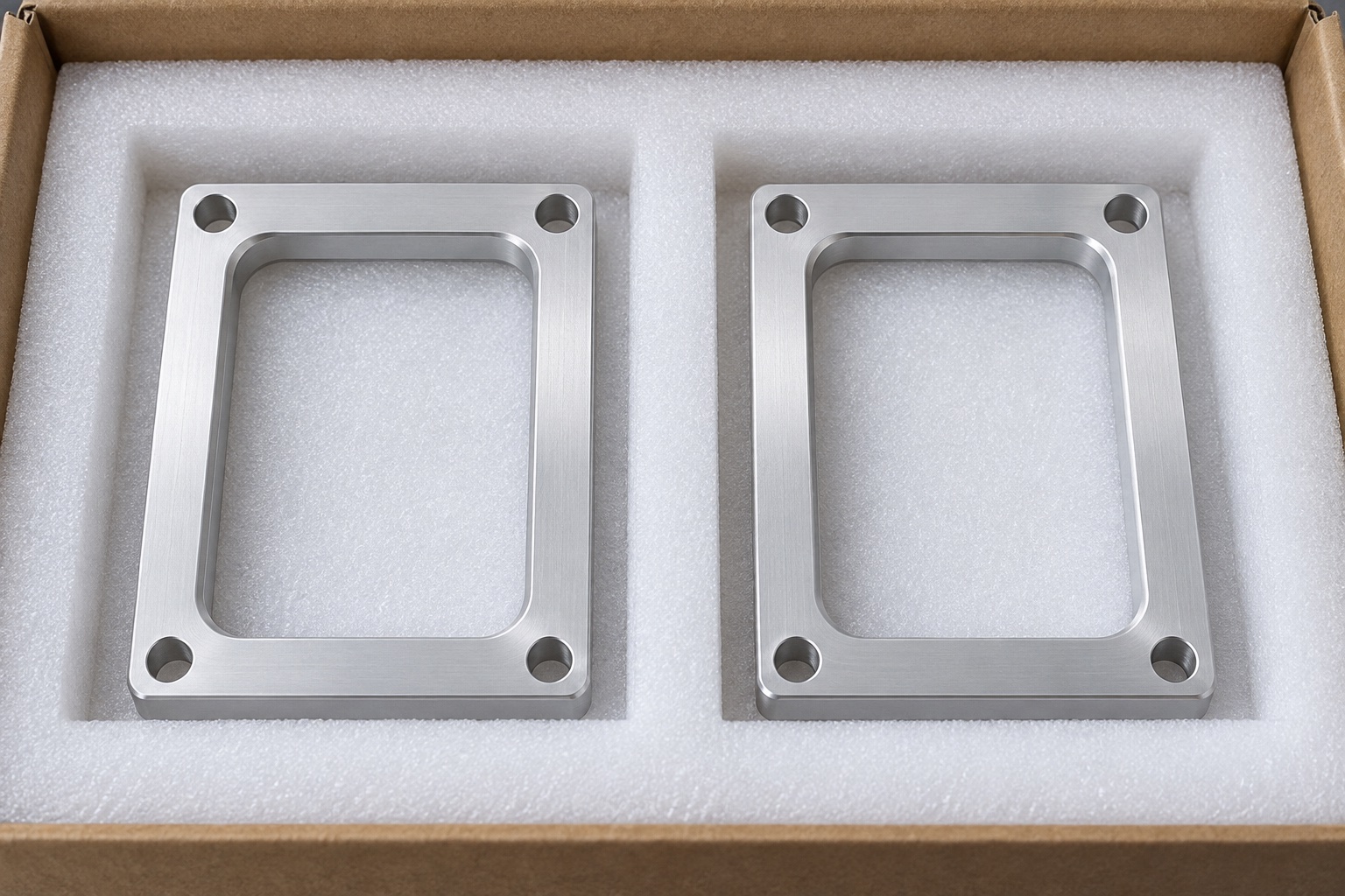
Finished frames would be separated in supports that protect contact lands, hole edges and opening boundaries. Pocket dimensions and restraint would avoid bending the rectangular ring or pressing loose hardware onto accepted surfaces. Mechanical transit protection would not imply sterile supply. Material lot, revision, treatment and inspection status would accompany the shipment. Receiving checks would distinguish frames with similar outlines but changed openings, thickness or mounting patterns. These controls would preserve the accepted component identity before installation and the equipment team's separate detector setup, cleaning and application evaluations within the actual medical laboratory instrument configuration.
Maintain an interface-specific production baseline
The final package would preserve released geometry, both mating components, useful contacts, opening clearance, mounting hardware, locating arrangement, material evidence, finished condition and inspection scope. Approved adjustments would become revised documents before another order. A changed detector housing, connector exit, support or coating would trigger review even if the outside frame size remained unchanged. This representative workflow demonstrates how a custom CNC frame project could be organized without inventing customer history, measured tolerances or shielding performance, and without confusing dimensional conformity of an aluminum component with qualification of the complete medical detector subsystem.
Manufacturer background reference: www.carrlane.com.
FAQ
Is this an actual delivered customer frame?
No. It is a representative proposed manufacturing workflow with illustrative component and process images. There is no customer delivery, manufactured sample, measurement report or achieved performance result. A real order would need its own released documents and production evidence.
Is the opening an approved optical aperture?
No optical specification is provided. It is a proposed mechanical clearance around a detector housing. Alignment, aperture definition, stray-light control and diagnostic performance must be defined and evaluated for the actual optical and equipment system.
Why are the mounting holes plain?
That is the defined geometry of this example. Threads or screw-head recesses would be different features and would need authorization. Actual hardware and locating arrangements would be reviewed rather than inferred from an illustration or convenient screw.
Does the inspection picture prove a tolerance?
No. It illustrates a possible arrangement. No actual measured values are available. An agreed inspection report would need identified characteristics, methods, references and the actual final component condition on a real manufacturing order.
Does this frame establish electromagnetic shielding?
No shielding or electrical continuity result is claimed. Those depend on the complete installation, contacts, finish and applicable equipment requirements. Aluminum identity and a rectangular outline are not sufficient qualification evidence.
What would trigger review on a repeat order?
Changes to detector housing, support, connector clearance, opening, lands, thickness, hole pattern, hardware, locating method or final treatment require review. Approved changes should enter controlled documents rather than remain in a manually fitted specimen.

tanghangyun@oemach.com