
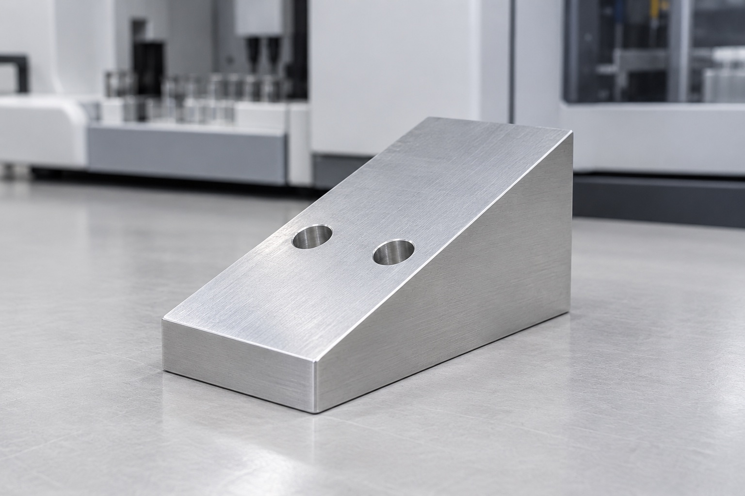
Representative proposed sensor mounting wedge
This representative example describes a proposed one-piece 6061 aluminum wedge for an equipment-side sensor carrier in a medical analyzer. Its illustrative shape has a flat rectangular underside, a thick low end, a taller opposite end and two plain through holes across the inclined upper face. Actual angle and attachment details would follow approved documents. This is not a customer delivery or measured part. No achieved tolerance, calibrated direction, detection result, thermal stability, electrical continuity, sterile status, medical certification or validated instrument performance is claimed as an actual production result.

Review the complete carrier configuration
The proposed order would begin with the controlled wedge drawing, sensor and carrier information, supporting structure, complete attachment arrangement and inspection requirements. The supplier would clarify which surfaces support, locate and retain the carrier, together with cable and fastener access. Missing base retention details would not be inferred from two illustrative holes. Any model and drawing conflicts would be resolved before cutting material. The manufacturing review would remain separate from the equipment team's sensor alignment, calibration and performance evaluation for its actual installation and intended medical analyzer configuration.
Retain the approved material condition
The material package would define the accepted 6061 condition, stock form, documentation and any final treatment. Blanks would remain traceable to the approved lot throughout milling, finishing and shipment. Similar appearance would not justify substituting another aluminum or changing the purchased finish. Stock allowance and holding regions would be reviewed before selecting the route. Material identity would support traceability, not establish cleaning compatibility, grounding performance or thermal behavior. Those requirements would need their own controlled acceptance scope if the actual sensor installation depended on them.
Establish the base before the slope
Initial operations would establish approved reference surfaces and holding contacts for the subsequent inclined-face work. The route would consider roughing, finishing, setup transfer and the component's released condition. The supplier would avoid accepting the wedge only while it was forced against a fixture. Chips would be removed from locating contacts before reorientation. Intermediate checks could inform process adjustments, but final acceptance would address the drawing's relationships between the useful mounting face, base, height and hole pattern after relevant machining and purchased surface processing were complete.

Machine the useful inclined mounting face
The inclined face would follow the approved angle, height, useful contact area and surface requirements. Tool access and fixture clearance would be reviewed before production rather than assuming every visible area was an acceptable holding contact. No angle would be selected from the illustrative photograph. The supplier would not lower or re-angle the surface merely to make an unidentified sensor appear aligned. Authorized changes would enter controlled documents, preserving a clear separation between component geometry and the calibrated direction or signal performance of the complete medical analyzer installation.
Produce the specified hole axes
The two holes would follow the released axis direction, position, diameter and entry requirements. A direction normal to the slope would not be replaced by a direction normal to the base for convenience. Any countersink, counterbore or thread would need its own approved definition; none is prescribed by the plain-hole concept. Setup planning would examine exit access and remaining material. Changed fasteners or an additional mounting feature would require authorization so subsequent wedges did not depend on an unrecorded sample or a machining interpretation that altered the actual carrier attachment.
Finish without changing the contact plane
Finishing would examine face boundaries, low-end edges and hole entries and exits for attached material or unwanted sharp features. Released edge requirements would preserve the useful contact plane and fastener contact areas. Cleaning and final treatment would follow the purchased scope with relevant finished-state checks. A visually smooth wedge would not establish measured particles, electrical contact, validated decontamination or sterile delivery. Uncontrolled polishing would not be used to hide surface damage or make one sensor carrier sit differently before the agreed dimensional report and any optional assembly observations were completed.
Plan related angle and position checks
The inspection plan would map angle, height, face, base and hole characteristics to accessible methods using the approved references. It would identify support, final treatment and useful contact regions. A simple slope reading and outside-size report would not automatically cover the hole-to-base relationship or specified face form. Ambiguous requirements would be clarified before production. The supplier and purchaser would agree the actual final-state acceptance method rather than substitute a favorable carrier-fit observation for all dimensions. Component reports would retain the identity and revision of the drawing they addressed.
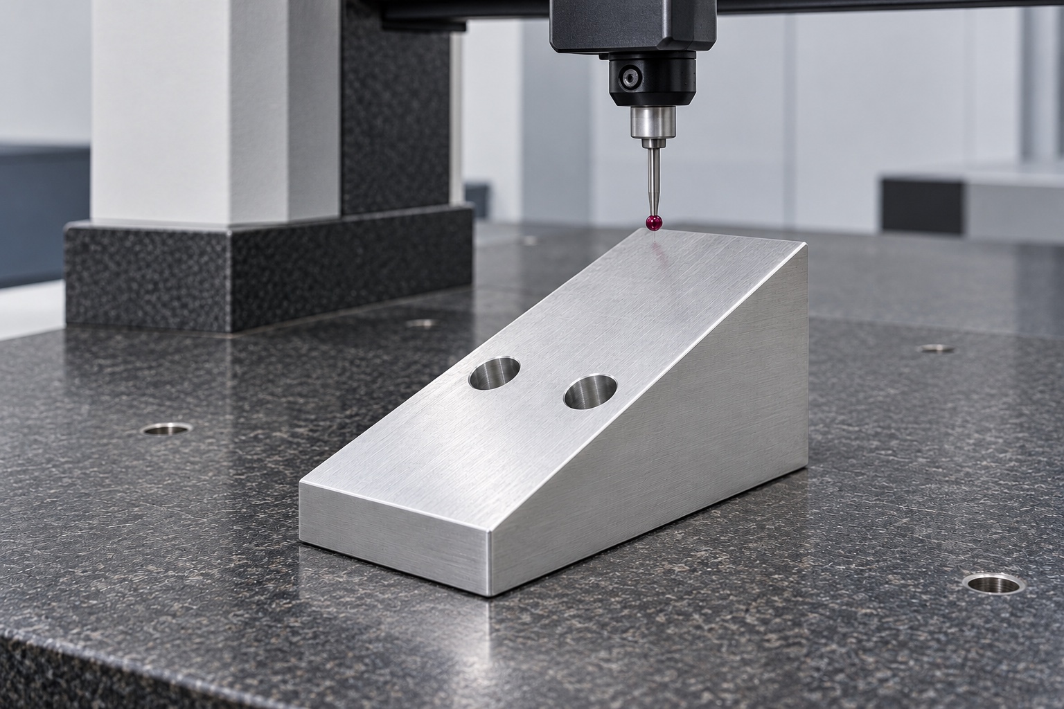
Prepare first-part evidence without invented values
The proposed report would identify material lot, drawing revision, numbered characteristics and agreed inspection methods. No measured values are provided because this example has no manufactured sample or production measurement record. Any actual nonconformance or authorized change would remain traceable. Accepted component dimensions would not prove sensor calibration, detection sensitivity or analytical accuracy. The record would distinguish completed dimensional checks from separate equipment evaluations and from observations made using an identified sensor carrier. A concept image would not be offered as evidence that a particular tolerance had been achieved.
Limit the optional installation demonstration
An agreed trial could examine carrier seating, fastening access, cable space and removal using identified sensor, carrier, wedge and support revisions. The method and any authorized adjustment components would be documented. Unexpected contact would be resolved before modifying the geometry. Successful hand assembly would not qualify optical alignment, thermal stability, vibration behavior or sensor performance. Trial wedges would remain separate from released production, and approved changes would enter revised documents rather than turning a hand-adjusted sample into an informal gauge for later orders with different sensors or support configurations.
Protect the accepted inclined surface
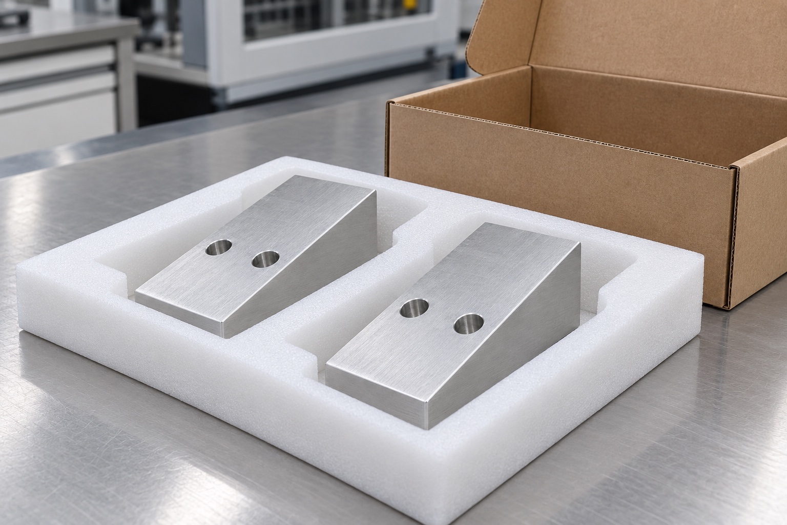
Finished wedges would be separated so neighboring parts and loose hardware could not strike the base, inclined face or hole entries. Packaging support would avoid loading a narrow region or trapping debris against accepted contacts. Protective packing would not imply sterile supply. Lot, revision, treatment and inspection status would accompany the shipment. Receiving checks would distinguish opposite slopes, different hole directions and modified prototypes. These controls would preserve component identity until the equipment team performed its separate installation, cleaning, alignment or calibration work under the actual approved analyzer configuration.
Maintain a controlled repeat-order baseline
The final package would retain the released drawing and model, carrier interfaces, complete attachment definition, angle and height references, material evidence, processing route, acceptance records and agreed packaging. Approved prototype adjustments would become revised documents. Changes in sensor, cable direction, support surface or final treatment would trigger review before another order relied on earlier observations. This representative workflow illustrates a traceable CNC scope without inventing customer history, guaranteed performance or a universal mounting design, and without confusing an accepted aluminum wedge with a calibrated or validated medical analyzer assembly.
Manufacturer background reference: www.thorlabs.us.
FAQ
Is this an actual delivered customer case?
No. It is a representative proposed CNC workflow, with illustrative component and process images. There is no named customer, manufactured sample, measurement record or achieved performance result. A real order would require its own released documents, production records and acceptance evidence.
Does this example prescribe a sensor angle?
No. The responsible equipment designer would define the angle, height and mounting references for the actual sensor and carrier. The image is not a dimensioned drawing and cannot be used to select a mounting angle or approve alignment.
Why does the hole direction need a separate requirement?
The axis affects attachment and setup planning. Holes normal to the inclined face and holes normal to the base are different configurations. The supplier would follow the approved direction instead of choosing a convenient axis from an illustrative concept.
Does material traceability establish thermal performance?
No. Traceability identifies the purchased material and condition. Thermal behavior, electrical contact, cleaning compatibility and other application properties would need their own requirements and evidence in the complete sensor installation, not an assumption based on 6061 aluminum.
What would first-part inspection demonstrate?
It would document the agreed dimensional characteristics in the specified final component condition. Actual results would need measurements linked to the drawing revision. Component conformity would not establish calibrated direction, detection sensitivity or the medical analyzer's analytical accuracy.
Would protective packaging mean sterile delivery?
No. The proposed packaging protects reference and mounting surfaces during handling and transport. Any quantified cleanliness, validated cleaning or sterile supply would require a separate purchased and verified scope. Neither the packing illustration nor a clean appearance establishes those conditions.

tanghangyun@oemach.com