
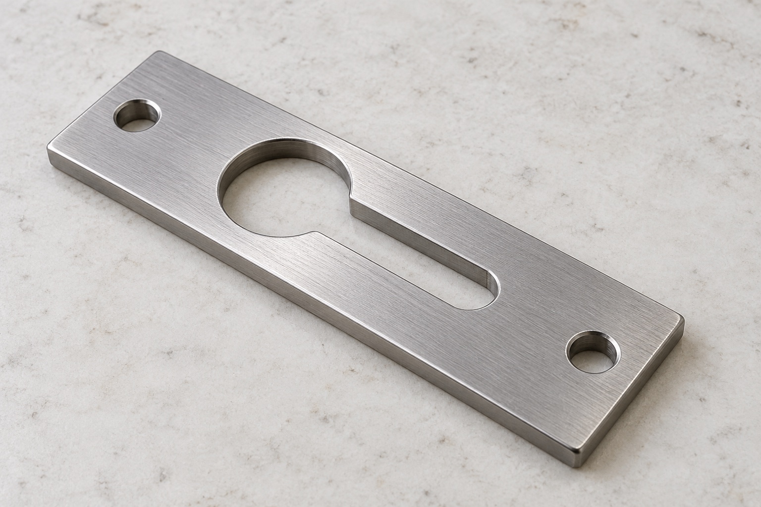
Representative proposed cover-retaining plate
This example considers a proposed one-piece 316L stainless plate for an equipment-side service-cover attachment in a medical instrument. Its illustrative geometry is a narrow rectangular plate with two end mounting through holes and a central through keyhole opening: one larger round entry connected to a narrower closed-end slot. Actual contacts and retention would follow approved assembly documents. This is a representative CNC workflow, not a customer delivery or measured latch. No achieved tolerance, retention capacity, release force, vibration result, sterile status, medical certification or validated equipment safety is claimed as an actual result.

Review the actual cover and hardware package
The proposed inquiry would begin with controlled model and drawing, exact hardware identity, head and shank geometry, cover and frame contacts, installation sequence and inspection deliverables. The review would distinguish insertion clearance from the neck's useful contact and identify any separate retention feature. Missing hardware or release requirements would be clarified before manufacture. Component machining and optional assembly demonstrations would remain separate from retention, vibration and safety evaluations assigned to the responsible medical equipment team for its actual complete cover arrangement and intended operating and service conditions.
Maintain the specified stainless identity
The material order would identify the approved 316L condition, stock form and evidence. Blanks would retain lot identity through machining, finishing, final processing and shipment. A similar-looking plate or catalog latch would not automatically be equivalent. The supplier would review allowance and support around the opening before selecting the route. Material substitutions would require authorization. Documentation would support the purchased component identity only, not establish another product's capacity, release behavior, corrosion result or suitability for every medical cover and hardware combination that could appear to accept a narrow keyhole plate.
Establish faces and mounting references
Initial machining would create the approved face and holding references needed to relate the entry, neck and two end mounting holes. Stock removal and setup transfers would be reviewed so the plate was not accepted only while forced flat against a fixture. Chips at locating contacts would be controlled before reorientation. The supplier would preserve the useful thickness and contact regions during later operations. Intermediate checks could support the route, but final acceptance would address the agreed component support and final surface condition after relevant machining and purchased treatment were complete.
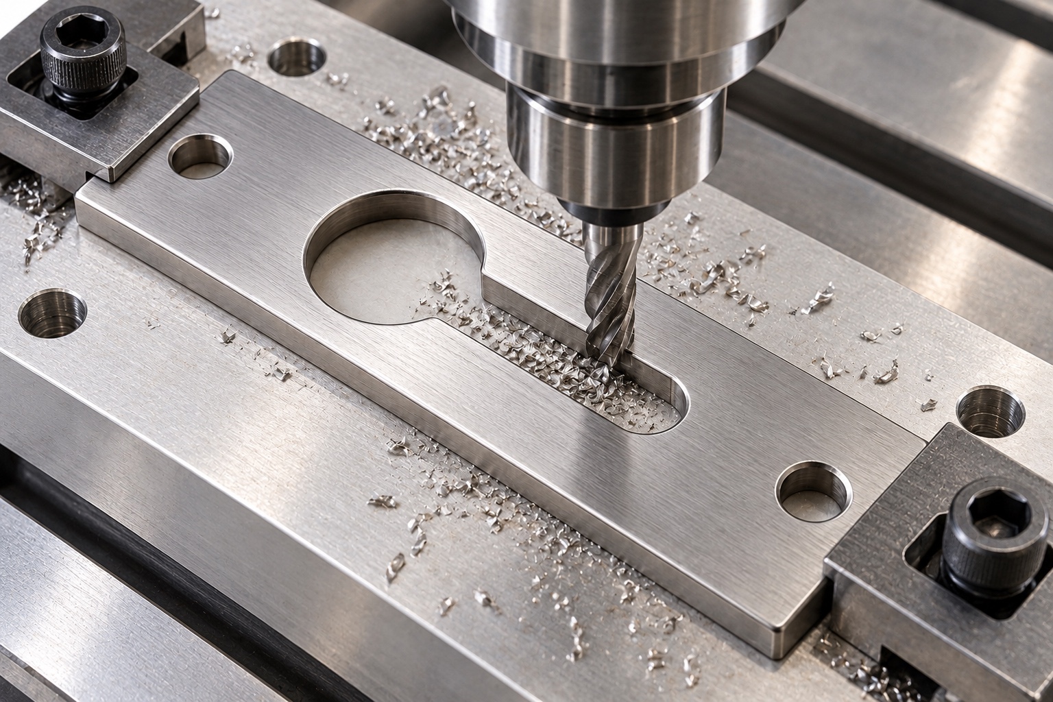
Machine the large entry and its transition
The entry opening would follow released size, position and edge requirements in relation to the actual hardware and mounting references. Tool access and permitted internal transition would be reviewed before production. The supplier would not enlarge the opening until an unidentified screw could enter. Any authorized adjustment would be incorporated into controlled geometry and inspection documents. The accepted entry would remain one defined part of the insertion path, not evidence that the cover could resist release, vibration or service loads in an unspecified medical equipment installation and hardware configuration.
Control the narrow closed-end sliding region
The neck width, useful length, end shape and relationship to the entry would follow the approved drawing and hardware definition. The supplier would distinguish clearance from useful under-head contact without assuming a locking function. Slot extension, shank modification or extra washers would not be introduced to improve a loose trial. Model and drawing conflicts would be resolved before machining decisions. Accepted changes would remain traceable so later orders did not depend on a particular screw sample, altered cover thickness or undocumented adjustment that concealed the actual installed contact and release requirements.
Preserve useful contact during finishing
The finishing sequence would examine entry and neck boundaries, mounting-hole exits and outer edges for attached material or unwanted sharp features. Removal would preserve useful under-head contact and the defined sliding width. Cleaning and any final process would follow the purchase scope, with relevant final-state checks. A bright surface would not establish corrosion performance, measured cleanliness, sterile delivery or a qualified locking function. Uncontrolled polishing would not conceal damaged geometry or transform the neck to suit one sample before the agreed dimensional and optional assembly observations were recorded.
Plan entry and neck inspection separately
The proposed inspection plan would identify methods for entry size, transition, neck width, useful travel, thickness and mounting relationships. Support and final treatment would be recorded. A screw passing through the opening would not verify every characteristic, and an outside rectangle alone would be insufficient. Ambiguous or inaccessible requirements would be clarified before production rather than replaced by a favorable cover demonstration. The report would identify what each method checked so component acceptance did not imply a measured retention capacity, release force or complete medical equipment safety evaluation for the installed assembly.
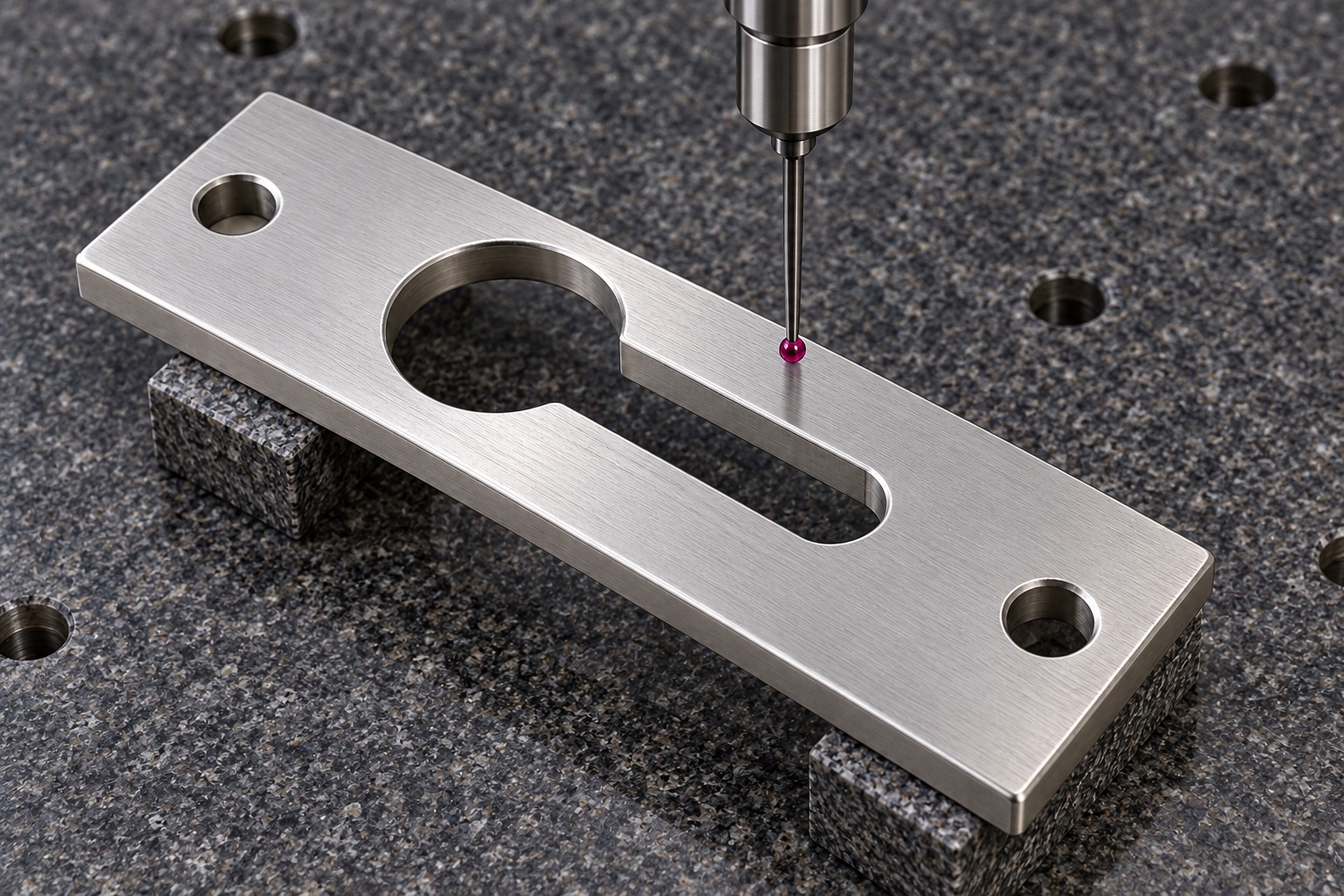
Prepare first-part evidence without invented data
The proposed report would identify drawing revision, material lot, numbered characteristics and agreed measurement methods. No numerical results are provided because this representative example has no manufactured sample or measurement record. Dimensional and material evidence would support only the purchased component scope. They would not demonstrate retention capacity, vibration resistance, wear life or equipment safety. Nonconformances and approved changes would remain traceable. A plate that could be assembled with a cover would not authorize omission of a controlled neck requirement or justify describing the complete installation as a tested medical locking system.
Define a limited cover assembly demonstration
An agreed trial could examine insertion, sliding, seating and specified release travel using identified hardware, cover, frame and plate revisions. Installation procedure and any separately approved retention feature would be recorded. Unexpected contact would be resolved before modifying geometry or adding parts. Successful hand assembly would not qualify holding capacity, release force, vibration, misuse resistance or equipment safety. Trial plates would remain distinct from accepted production. Observations would enter controlled change records rather than become an informal gauge or approval for another cover thickness, hardware type or medical instrument service configuration.
Package slot boundaries and thin regions
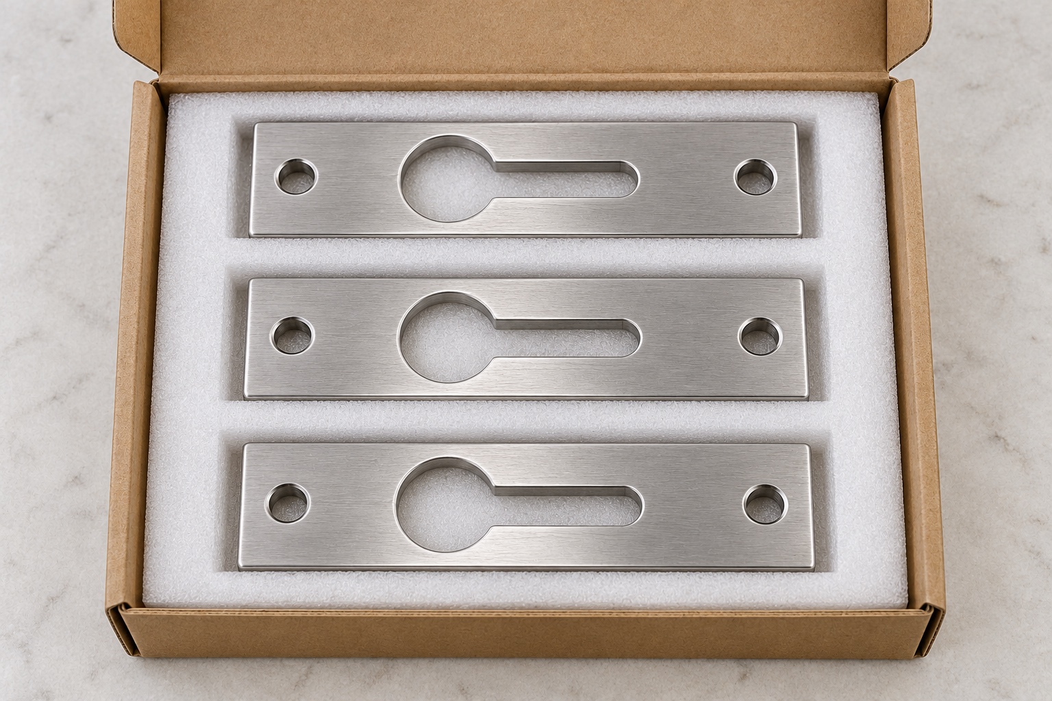
Finished plates would be individually separated so studs, neighboring edges and packaging debris could not strike the neck or entry transition. Support would avoid unnecessary bending pressure. Protective materials would match the agreed cleaning scope without implying sterile supply. Grade, material lot, final process, thickness variant, revision and inspection status would accompany the shipment. Receiving personnel could distinguish released parts from modified trial plates and visually similar retainers before assembly or service stock was populated, preserving the controlled baseline for installation and separately defined retention or equipment-level evaluations.
Retain the cover-specific repeat-order baseline
The proposed baseline would preserve geometry, exact hardware, contact stack, release path, material evidence, machining sequence, final treatment and inspection scope. Repeat orders would review changed screw heads, cover thicknesses, additional retention features or service procedures before relying on previous observations. Component acceptance would remain separate from assembly qualification. This case explains how a CNC supplier could document a shaped retaining interface without inventing a customer delivery, achieved tolerance, rated capacity, vibration result or medical certification for an illustrative 316L plate and an unspecified complete medical equipment service-cover arrangement.
Manufacturer background reference: www.dranetz.com.
FAQ
Is this a tested medical cover latch?
No. It is a representative proposed machining example without an actual delivery or measured sample. No achieved tolerance, retention capacity, release force, vibration result or medical certification is presented as an actual result for the illustrated retaining plate.
What defines the keyhole opening?
The approved drawing and exact hardware define the larger entry, transition, narrow neck and useful travel. The illustration does not establish a locking function, universal screw compatibility or permission to change the opening until a prototype slides easily.
Can a similar screw replace the approved hardware?
Not automatically. Head and shank geometry, under-head clearance and contact stack may differ. The responsible designer must approve substitutions; an apparently favorable loose fit should not establish compatibility or an undocumented machining change for subsequent retaining plates.
What would first-part inspection establish?
It would document agreed component characteristics with identified revision, material, methods and final condition. It would not independently establish retention, vibration resistance, release force, wear life or the safety of the complete medical equipment cover and hardware arrangement.
Can insertion and release be demonstrated?
Yes, when hardware, cover, frame, revisions, procedure and exact checks are agreed. Keep mechanical observations separate from retention and equipment qualification, and resolve unexpected contacts before authorizing modifications or adding parts to the controlled assembly.
What should another production batch review?
Review hardware, entry and neck geometry, thickness stack, release travel, additional retention features, material and treatment. Preserve controlled revisions instead of recreating a hand-adjusted plate or transferring another instrument's rated capacity, vibration or safety claims to this illustrative component.

tanghangyun@oemach.com