
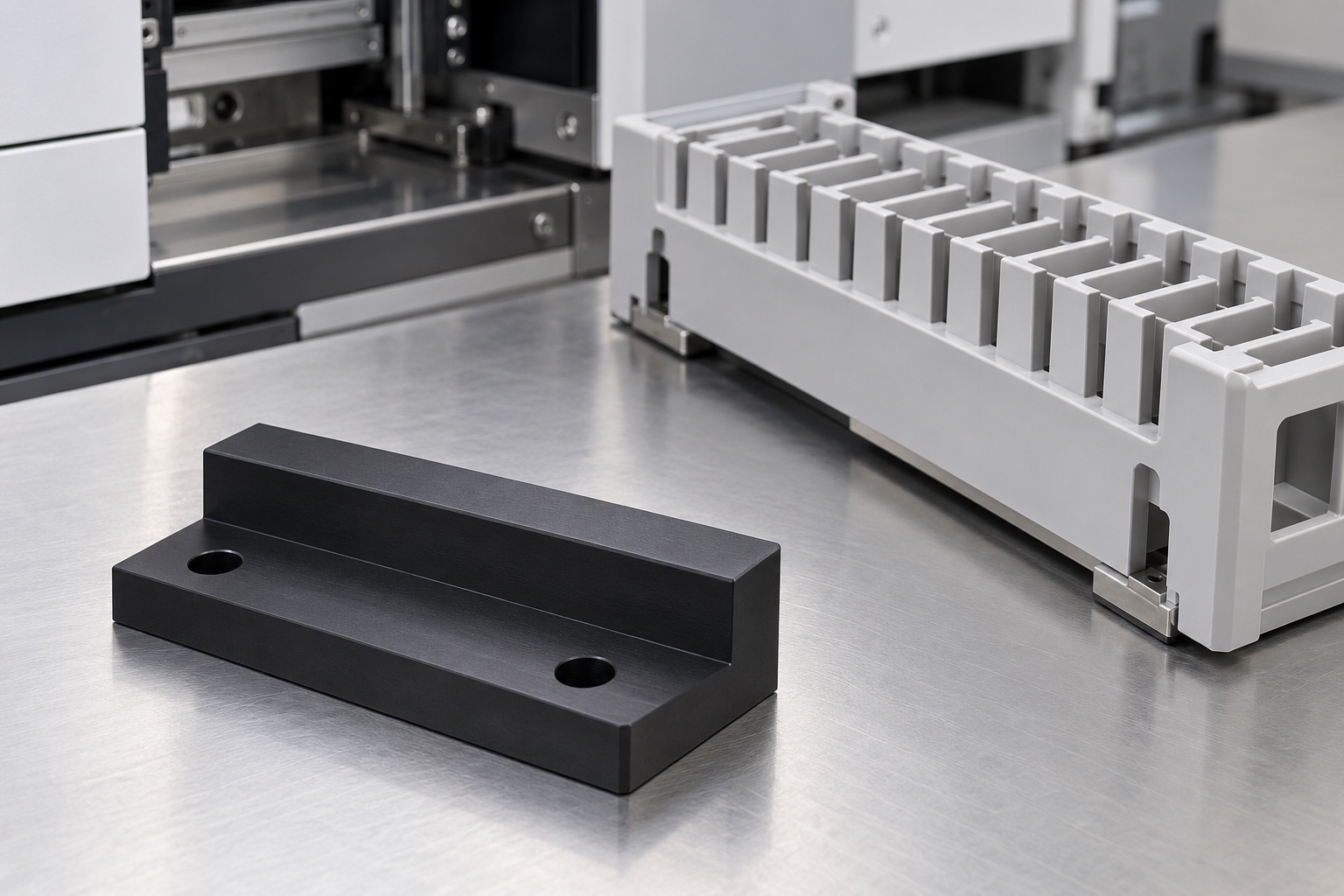
Representative proposed rack-carrier locator
This example considers a proposed black POM locator shoe for an equipment-side medical laboratory rack carrier. It is a low rectangular stepped block with a broad base, raised rear contact region and two mounting holes on a lower ledge. The approved carrier would define actual support and location functions. This is a representative CNC workflow, not a delivered customer part or measured result. No achieved tolerance, rack-positioning accuracy, wear life, sample-integrity outcome, sterile status, medical certification or equipment-safety result is claimed for the illustrated polymer component.

Review the defined carrier and contact scheme
The proposed order would start with controlled geometry, exact rack-carrier identity, mounting structure, contact intent, insertion envelope and inspection deliverables. The review would distinguish the horizontal support region, side contact and surfaces required to remain clear. Missing requirements would be clarified before costing and machining. An empty generic rack sample would not define the complete interface. Component manufacture and optional carrier demonstrations would remain separate from independent positioning, sample-handling and equipment evaluations assigned to the responsible analyzer design program and its actual installed configuration.
Maintain the prescribed polymer identity
The material order would identify the actual approved black POM grade, stock form, condition and evidence. Lot identity would remain with cut blanks through milling, finishing and shipment. A similar-looking plastic offcut would not automatically be accepted as equivalent. The supplier would review machining allowance and base support before choosing the route. Substitutions would require approval before use. Stock-material properties would not become measured wear or cleaning results for the finished shoe, and material identity alone would not qualify every carrier contact or medical laboratory service environment.
Create the base and mounting references
Initial operations would establish the approved base contacts and locating references used to relate the raised step and mounting holes. Broad workholding would preserve these relationships without force-flattening the block. Chips on fixture faces would be controlled before setup transfers. The supplier would consider how material removal affected support and avoid using an unfinished raw edge as an unintended datum. Intermediate checks could confirm the route, but final acceptance would address the shoe in the agreed measuring and support condition after manufacture and any required conditioning.
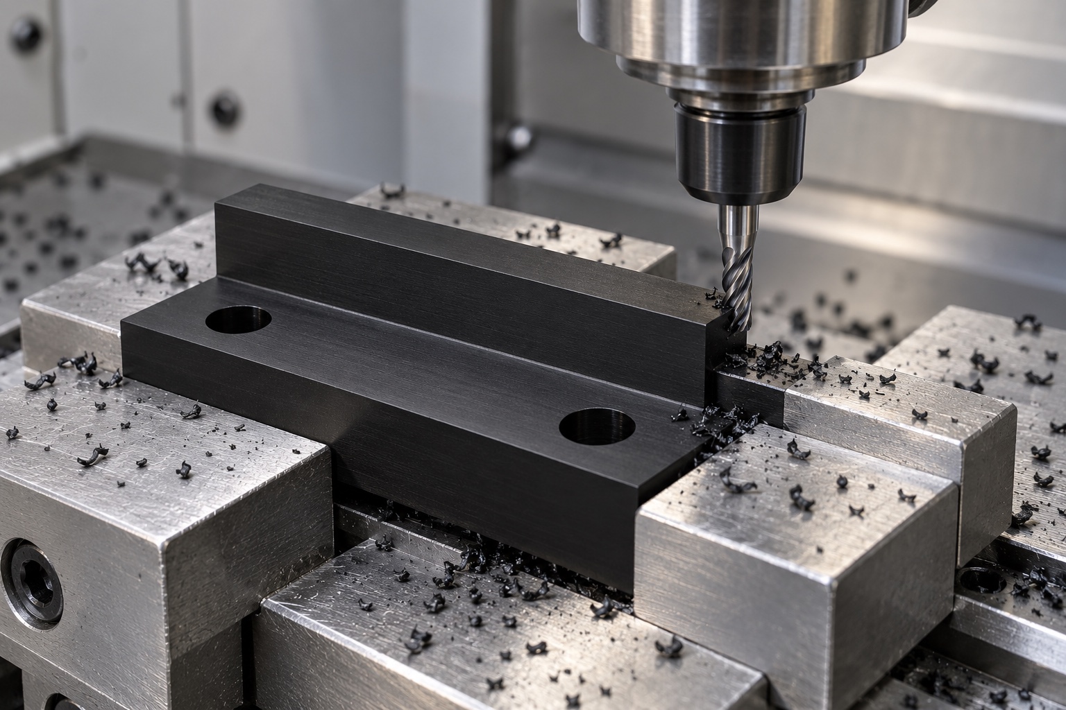
Machine the released step contacts
The step height, side-contact position, useful length and transitions would follow the approved drawing and carrier information. Tool access and internal radii would be reviewed before production so a convenient cutter did not create an unexpected contact. A proposed relief would need design approval when it changed controlled geometry. The supplier would not scrape the side face until an unidentified rack could be inserted easily. Authorized modifications would enter controlled manufacturing and inspection documents. The accepted component would remain distinct from assumptions about positioning repeatability or the analyzer's sample-handling performance.
Keep mounting and entry geometry coordinated
The two holes and their seating areas would be produced in the agreed relationship to the contact step and base. The carrier's approach path and available fastener tools would be reviewed with the mounting structure. The supplier would not introduce slots, substitute screws or extra adhesive to correct an unspecified installation. Model and drawing conflicts would be clarified before production decisions. Any accepted change would be documented so later batches did not depend on a particular operator's hand fitting, tightening preference or a carrier sample different from the approved configuration.
Finish boundaries without reducing useful contacts
The finishing operation would examine step transitions, hole exits and outer boundaries for attached material or unwanted sharp edges. Removal would preserve contact height, length and position rather than round all features indiscriminately. Uncontrolled scraping, polishing, thermal smoothing or solvent treatment would not conceal tool marks or create a favorable demonstration. Cleaning would follow the purchased scope. A smooth black surface would not establish a particle-generation limit, validated disinfection, sterile delivery or a measured wear result, and markings would remain in approved areas away from functional contacts.
Agree the unloaded measurement condition
The dimensional plan would define base support, functional references, measuring force and any required conditioning for the selected polymer. Methods would address the step, contact faces, base and mounting relationships rather than only overall size and hole diameters. Free-state requirements would not be replaced by excessive holding force. An installed carrier check would have separately agreed configuration and meaning. Inaccessible or ambiguous features would be clarified before production so a successful insertion did not silently substitute for a controlled dimension or turn a particular rack sample into a universal inspection gauge.
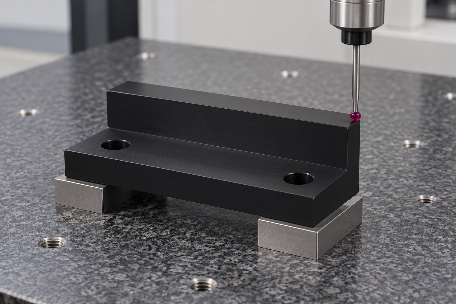
Prepare traceable first-part evidence
The proposed report would connect drawing revision, polymer lot and numbered characteristics to the agreed inspection methods and support conditions. No numerical results are provided because this representative case has no manufactured sample or measurement record. Material and dimensional evidence would support acceptance within the purchased component scope only. It would not demonstrate rack-positioning accuracy, sample identification, contamination control, long-term wear or laboratory equipment safety. Ambiguous contacts would be resolved before production rather than treated as accepted because an empty carrier appeared to sit in place during an informal demonstration.
Define an optional carrier-fit demonstration
An agreed trial could check insertion, resting contacts, removal and specified clearances with identified carrier and equipment revisions. Installation conditions would be recorded. Unexpected contact would be documented before modifying the shoe or carrier. A successful hand-operated demonstration would not qualify positioning repeatability, wear, cleaning, sample integrity or equipment safety. Trial shoes would remain traceable and distinct from accepted production. Their observations would not become an informal gauge or an undocumented replacement for drawing-defined acceptance when another carrier, mounting arrangement or sample-handling configuration was introduced later.
Package contacts and identify demonstration parts
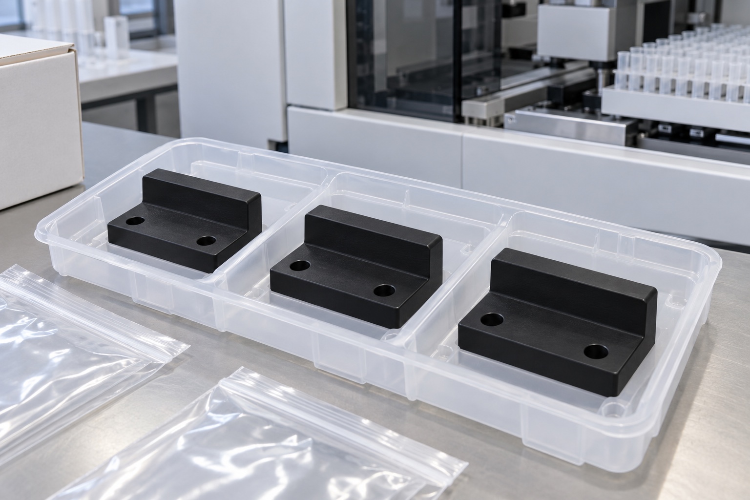
Finished shoes would be individually supported or separated so step contacts and bases could not rub neighboring components or loose hardware. Packaging pressure would not bend the block. Protective materials would match the agreed cleaning scope without suggesting sterile supply. Polymer, lot and revision identity would remain with the shipment. Any demonstration carrier would be identified separately. Receiving personnel would distinguish released components from prototypes and similar locator blocks intended for another contact scheme, mounting pattern, step height or medical laboratory equipment installation before assembly or maintenance use.
Maintain a carrier-specific production baseline
The proposed record would preserve geometry, approved carrier information, stock evidence, machining route, contact and edge requirements, final condition, inspection deliverables and authorized changes. Repeat orders would review carrier contacts, insertion path, mounting hardware, polymer and cleaning exposure before relying on earlier observations. Dimensional acceptance would remain separate from rack and analyzer qualification. This representative case explains how a CNC supplier could document a defined carrier interface without inventing a customer delivery, measured process capability, wear test, sterile claim, sample-integrity result or medical certification for an illustrative black POM component.
Manufacturer background reference: www.ensingerplastics.com.
FAQ
Is this a delivered or validated laboratory locator?
No. It is a representative proposed machining example without an actual delivery or measured sample. No achieved tolerance, positioning accuracy, wear life, sterile status, sample-integrity result or medical certification is presented as an actual outcome.
What defines the raised step and side contact?
The approved drawing, carrier identity, mounting references and contact scheme define those features. A generic empty rack, nominal step height or illustrative photograph should not replace the actual installed interface and clearance requirements.
Can a replacement rack justify hand adjustment?
Only after controlled review and authorization. Changed carrier geometry can affect contacts and insertion, so an undocumented scrape or enlarged hole should not become a production instruction or be transferred to another rack configuration.
What would first-part inspection establish?
It would document the agreed component characteristics using traceable revision, material, methods and support conditions. It would not demonstrate positioning repeatability, sample integrity, cleaning, wear or equipment safety without separately defined procedures and evidence.
May a carrier trial be included?
Yes, when carrier, equipment, revisions, mounting and exact checks are agreed. Keep insertion and resting-contact observations separate from positioning or laboratory-process qualification and resolve unexpected interference before authorizing geometry changes.
What should be reviewed before another order?
Review carrier identity, contact surfaces, step height, insertion envelope, mounting, polymer and cleaning scope. Retain authorized revisions instead of recreating a hand-adjusted locator or automatically reusing observations from another laboratory rack arrangement.

tanghangyun@oemach.com