
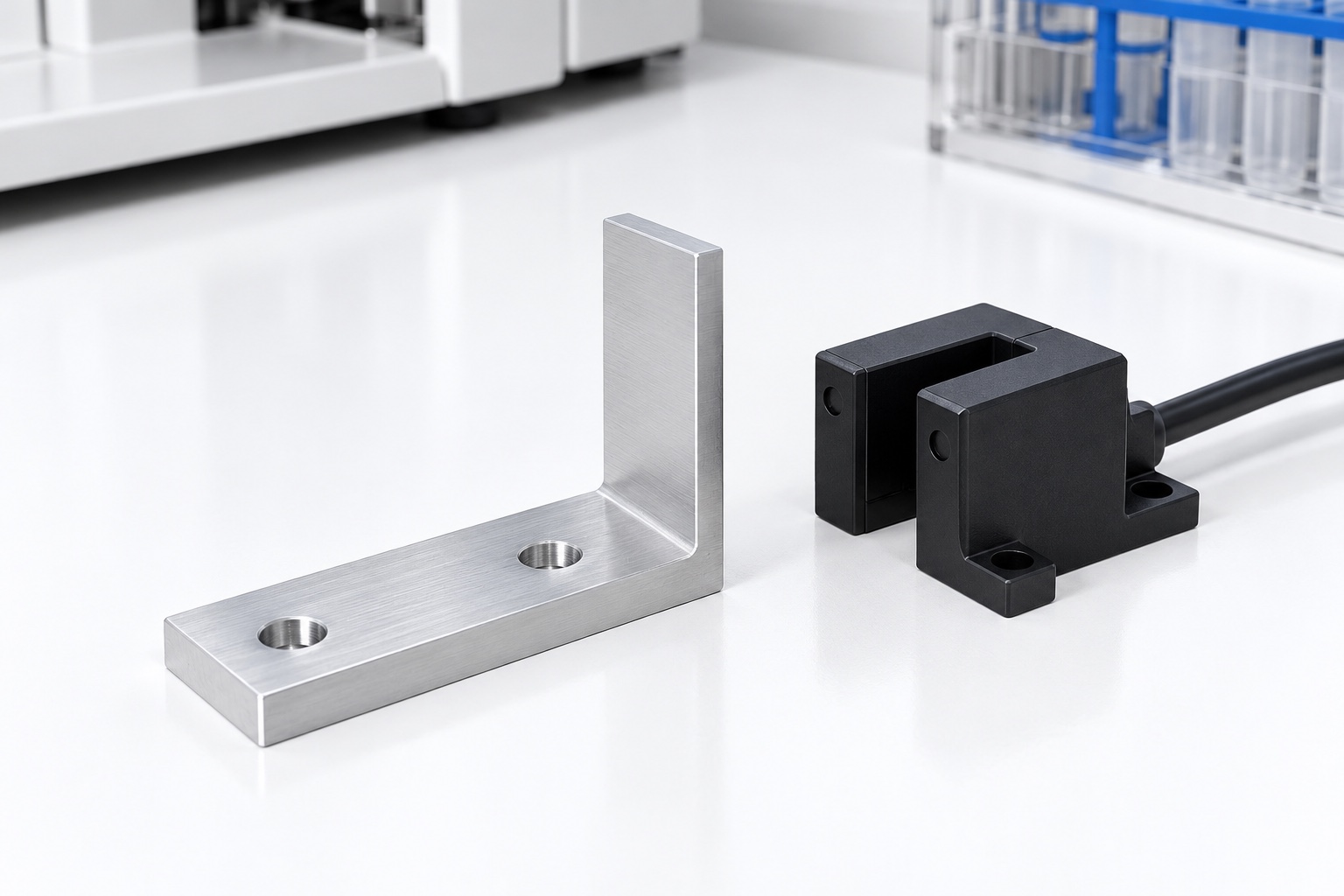
Representative proposed analyzer target
This example considers a proposed one-piece 6061 aluminum bracket for a medical analyzer carriage. It has a rectangular mounting foot with two clearance holes and an upright solid vane at one end. The vane is intended as a target for a separately specified slot sensor. This is a representative manufacturing workflow, not a customer delivery or measured production result. Images illustrate geometry. No achieved tolerance, switching repeatability, certified safety function, equipment approval or validated optical performance is claimed for the proposed component.

Begin with a defined installed configuration
The proposed order would start with the controlled model and drawing, approved sensor identity, carriage contacts, entry direction and movement envelope. The review would distinguish sensing edges from assembly-clearance surfaces and identify where the aperture crosses the vane. Missing installation requirements would be clarified before manufacture. A loose sensor sample would not establish every target requirement. The purchased scope would separate machining and dimensional acceptance from any optional mechanical demonstration and from electrical or control-system evaluations assigned to the responsible equipment program.
Keep aluminum identity and condition traceable
The material order would specify the approved 6061 condition, stock form and documentation. Lot identity would remain associated with blanks through machining, final processing and shipment. Similar-looking aluminum offcuts would not automatically qualify as substitutes. The supplier would review machining allowance and fixture support before choosing the route. Any substitution would require authorization. Material evidence would support the purchased component scope but would not establish sensor response, environmental behavior or equipment safety, and the illustrated bare surface would not prescribe an unapproved final treatment.
Establish mounting-foot references first
Initial operations would create the released foot contacts and locating references used to relate the two holes to the upright vane. Workholding would preserve those relationships without bending the base or pressing the vane into an artificial inspection position. Fixture contacts would be cleaned before transfers. A convenient stock edge would not silently replace a functional datum. Intermediate measurements could confirm the route, but final acceptance would use the agreed component state rather than relying on dimensions recorded only while substantial holding force was applied.
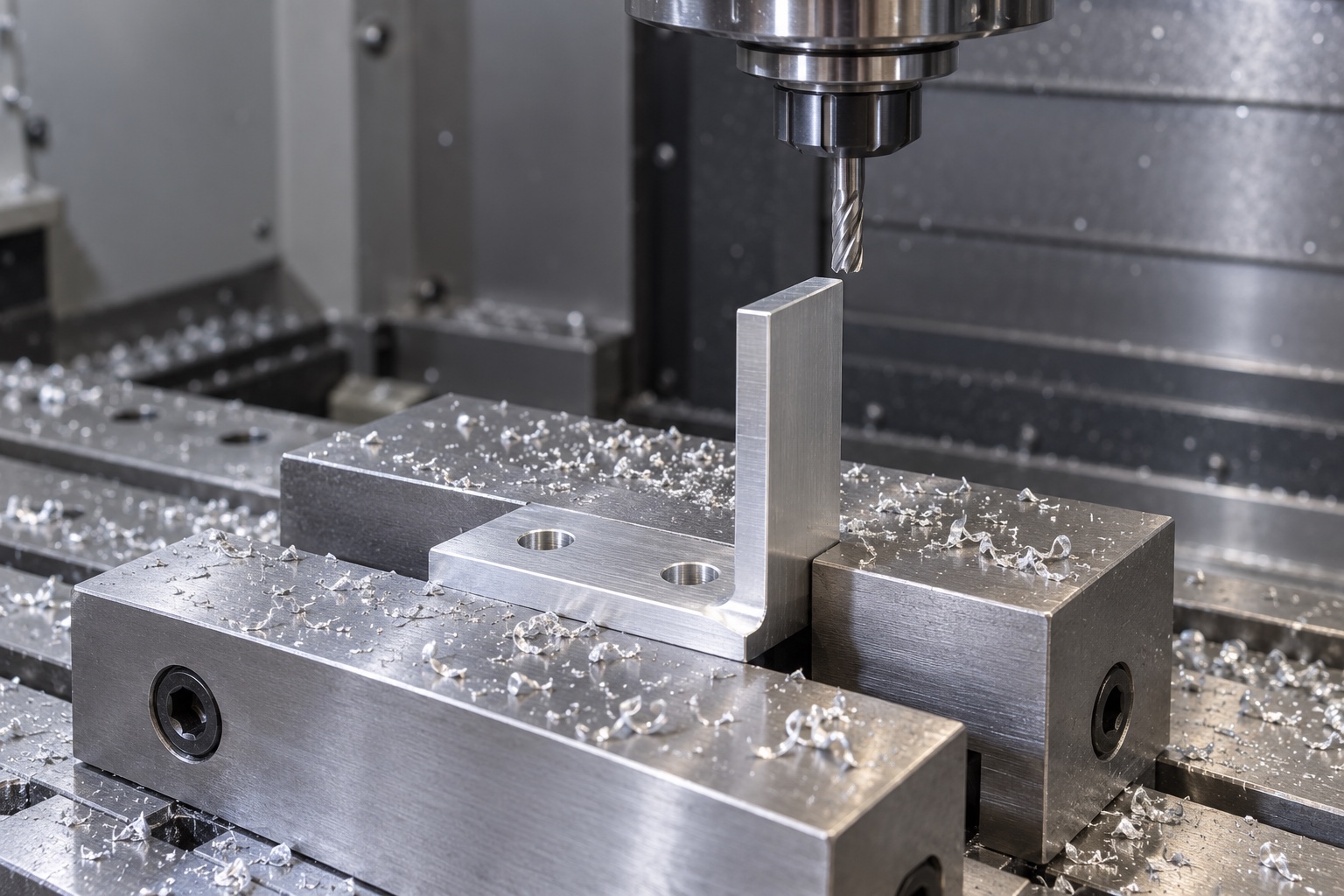
Machine the controlled vane and target edges
The vane thickness, height, orientation and sensing-edge positions would follow the approved geometry. The machining sequence would account for the reduced support of the upright feature as surrounding material was removed. Cutter access and the inner corner would be reviewed before production. A radius change or extra reinforcing feature would need approval if it changed released geometry. The supplier would not file the vane to obtain one successful switching demonstration. Accepted changes would enter controlled manufacturing and inspection documents before being transferred to production.
Maintain holes and installed access
The mounting holes would be produced in the agreed relationship to the foot and vane rather than located from an unfinished outside corner. Their clearance function would remain distinct from any separate locating interface. Fastener access, seating and neighboring sensor clearance would be reviewed together. The supplier would not introduce a slot, counterbore, washer or adhesive without authorization. Conflicting installation information would be resolved before cutting, so the manufactured bracket would not depend on an undocumented screw substitution or an operator forcing the target into position.
Preserve the target during finishing
The finishing sequence would examine the vane perimeter, foot transition and hole exits for attached material or unwanted sharp edges. Removal would follow the approved edge definitions and preserve the target's effective boundary. Aggressive polishing would not be used to hide distortion or redefine a sensing edge. Cleaning would follow the purchased scope. Any approved coating or other final treatment would have documented coverage and inspection requirements. Surface appearance would not become a claim of quantified cleanliness, sterile delivery or tested optical behavior in a complete medical analyzer.
Inspect the final component without bending it
The plan would use approved mounting references and suitable methods for vane faces, sensing edges, thickness and hole relationships. Probe access and measuring force would be reviewed so the method did not move the upright feature. Support and final-treatment state would be recorded. Outside size alone would not establish the target envelope. Inaccessible or ambiguous requirements would be clarified before production, not replaced by a convenient height reading or a sensor that happened to switch once during a loosely controlled tabletop demonstration.
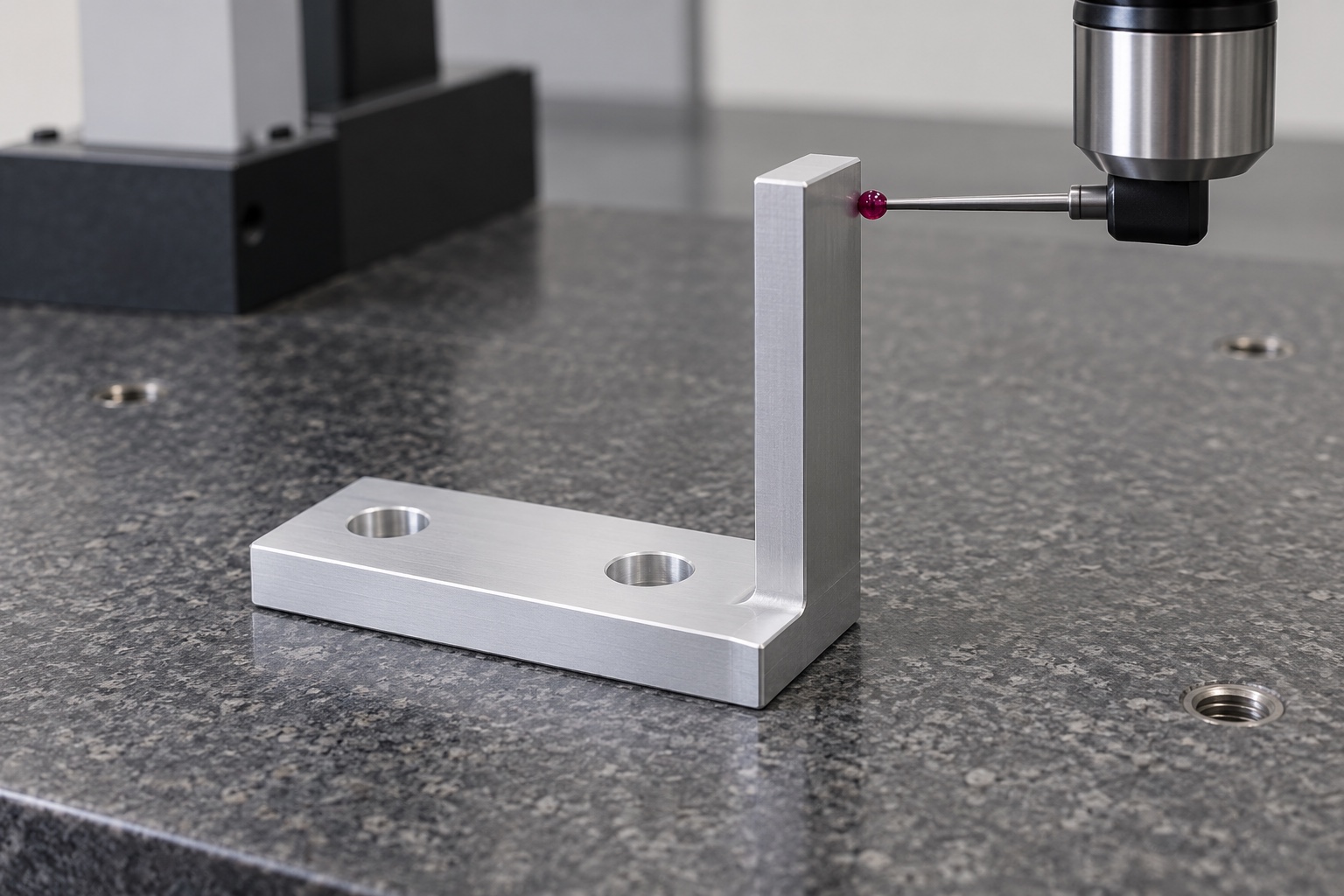
Document evidence without inventing measurements
A proposed first-part report would connect drawing revision, material lot and numbered characteristics to agreed inspection methods. No numerical results are provided because this example has no manufactured sample or measurement record. The report would support component acceptance within the agreed scope, not demonstrate positioning accuracy, switching repeatability, electronic timing or equipment safety. Nonconforming geometry would remain a documented issue. A sample that could be assembled would not authorize omission of a specified target-edge, hole-pattern or final-condition inspection from the accepted production record.
Define an optional mechanical fit trial
An agreed demonstration could check mounting, screw access and clearance through the specified movement using identified sensor and carriage revisions. Unexpected contact would be documented before changing the bracket or installation. Detection and control tests would remain separate approved activities; a visible switching event would not qualify the whole mechanism. Trial components would remain traceable and distinguishable from accepted production. Any authorized changes would enter released documents rather than leaving a hand-adjusted bracket as an informal master for later CNC batches or another sensor configuration.
Package the upright geometry protectively
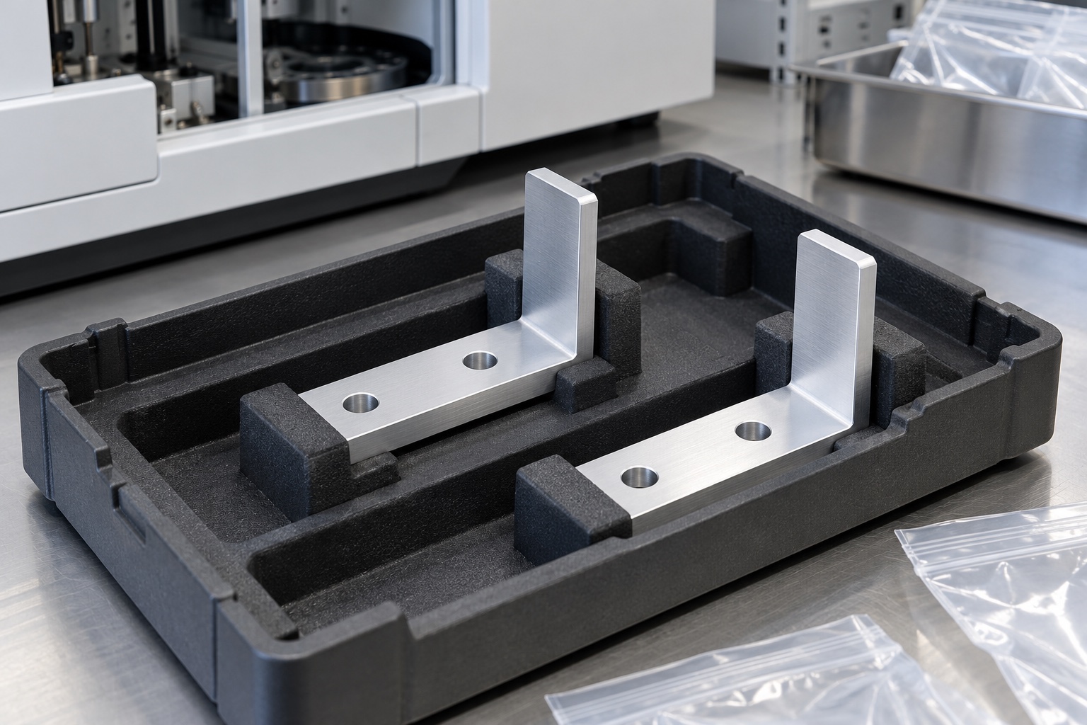
Finished brackets would be individually separated and supported under the mounting foot. The tray or bag would keep adjacent parts and loose hardware away from the vane and sensing edges. Packaging pressure would not bend the target. Protective materials would match the agreed cleaning scope without suggesting sterile supply. Material, treatment, lot and revision identity would remain with the shipment. The receiver would be able to distinguish released analyzer brackets from prototypes and similar targets intended for a different sensor slot, carriage interface or entry direction.
Maintain a controlled repeat-order record
The proposed baseline would retain geometry, approved sensor documents, stock evidence, manufacturing sequence, edge definitions, final processing, inspection scope and authorized changes. A repeat order would review changed sensors, apertures, travel, mounting contacts and treatment before relying on prior observations. Component acceptance would remain separate from detection qualification. This representative case explains how a CNC supplier could document an analyzer target without inventing a customer, achieved process capability, switching result, medical certification or validated safety claim for an illustrative aluminum bracket and a generic slot-sensor installation.
Manufacturer background reference: components.omron.com.
FAQ
Is this an actual delivered sensor bracket?
No. It is a representative proposed CNC example without a customer delivery or measured sample. The article makes no achieved tolerance, switching repeatability, medical certification or equipment-safety claim for the illustrated bracket.
What defines the vane position?
The approved drawing, mounting references, sensor aperture and installed movement define the target relationship. Nominal bracket height or a photograph should not replace the actual carriage and sensor interface requirements.
Can a matching-looking sensor be substituted?
Not automatically. Slot geometry, aperture position, mounting and response may differ. The responsible equipment team must approve the changed configuration; informal sample fit should not establish compatibility or become a production instruction.
What would first-part inspection show?
It would document the agreed component geometry with traceable revision, material, method and final condition. It would not establish electronic response, optical switching repeatability, controller behavior or medical equipment safety without separately defined evaluations.
May a mechanical demonstration be included?
Yes, when components, revisions, movement and exact checks are agreed. Keep clearance and seating observations separate from detection validation, and resolve unexpected contact before introducing an authorized geometry change.
What should be checked before another batch?
Review sensor identity, aperture, motion, mounting stack, sensing edges, material and final process. Preserve controlled changes instead of requesting a copy of an undocumented hand-fitted bracket or transferring another installation's results.

tanghangyun@oemach.com