
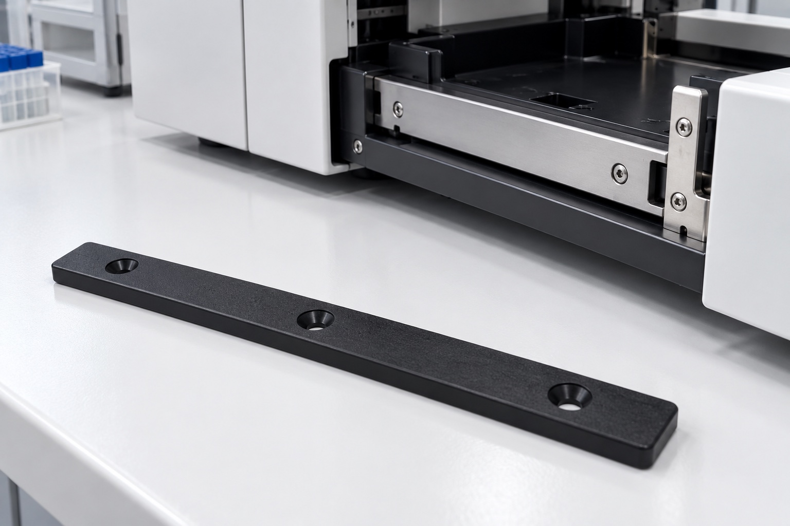
A representative proposed wear strip
This example considers a proposed black POM wear strip for a medical equipment service drawer. It is a long rectangular component with a sliding face, mounting face and three recessed mounting holes. The example illustrates a possible CNC workflow, not an actual customer delivery, load-rated slide or validated medical device. Images show concepts rather than measured results or wear tests. Final material grade, mating surface, fastening arrangement and acceptance requirements would need approved project documents. No friction coefficient, service life, particle result, allowable drawer load, certification or achieved tolerance is claimed for the proposed component.

Review the complete contact and support package
The proposed order would begin with controlled drawings and model, the drawer's mating surface, support arrangement, approved screws and relevant travel clearances. The review would distinguish sliding contact from mounting contact and deliberately clear regions. Missing information about recesses, support spacing or inspection condition would be clarified before costing and route planning. An isolated sample bracket would not define the entire installation. The purchased scope would separate dimensional manufacture, optional assembly trials and any independent wear, load, environmental or device-level evaluation assigned to the responsible equipment program.
Preserve the approved polymer identity
The material order would identify the actual approved black POM grade, stock form and required evidence. Appearance would not establish material identity or performance equivalence. Lot information would remain associated with cut blanks through machining, finishing and packaging. The supplier would not turn a typical datasheet property into a measured result for the finished strip. Any proposed substitute intended to improve availability or cost would require authorization before use. Application suitability would remain a design decision based on the complete combination of contact materials, load, environment and cleaning process rather than generic color or polymer family.
Establish broad support and references
Initial operations would establish the mounting and sliding-face references needed for subsequent features. Workholding would support the strip along the relevant length without forcing it into a false shape. Chips and polymer remnants at fixture contacts would be controlled before transfers. The supplier would consider how material removal and local clamping affect the narrow geometry. Intermediate checks could confirm the route but would not substitute for final acceptance. The intended result would be repeatable geometry in the specified measurement condition, not one apparently straight sample held by excessive fixture pressure during inspection.
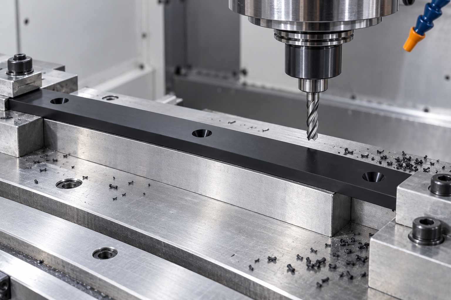
Machine the controlled sliding relationship
The route would preserve the drawing-defined relationship between sliding face, mounting face and any relevant end references. Tool access and edge transitions would be reviewed before production. A convenient raw edge would not silently become the acceptance reference. The supplier would not remove material informally to match an unapproved drawer sample. An accepted geometry change would enter the controlled documents and corresponding inspection requirements. The process would distinguish dimensional manufacturing from assumptions about how long the contact lasts or how the full drawer behaves under operating loads and maintenance conditions.
Produce recesses for the approved fasteners
The three mounting holes and their specified recesses would follow the approved screw arrangement and references. The review would address head seating, remaining material, tool access and clearance to the intended sliding path. A recess would not be deepened until a random screw happened to look flush. The supplier would resolve model and drawing discrepancies before making production decisions. Any authorized screw or recess change would be recorded and reflected in inspection, rather than remaining a hand-fitted prototype detail that later production personnel had to reproduce from memory or appearance.
Finish polymer contact transitions deliberately
The finishing process would inspect the strip ends, long edges, hole exits and recess boundaries for attached material or unwanted sharp transitions. Removal would remain within approved geometry and preserve the functional contact area. Uncontrolled scraping, thermal smoothing or solvent treatment would not be introduced simply to improve movement in a sample assembly. Markings would stay in approved locations. Cleaning would follow the purchased requirements, and a damaged sliding face would be handled as a component issue rather than hidden by polishing, a protective film or a successful hand-operated drawer demonstration.
Agree the actual measurement condition
The inspection plan would specify support locations, reference arrangement, measuring force and any environmental conditioning needed for the polymer. The supplier would choose methods appropriate for the face relationships, thickness, recesses and mounting features before production. A length and hole-spacing report alone would not verify the complete controlled interface. If the drawing required free-state geometry, the strip would not be forced flat to generate acceptance data. Any installed or loaded condition would have a separately defined method and meaning instead of replacing the component's specified unloaded requirements without acknowledgment.
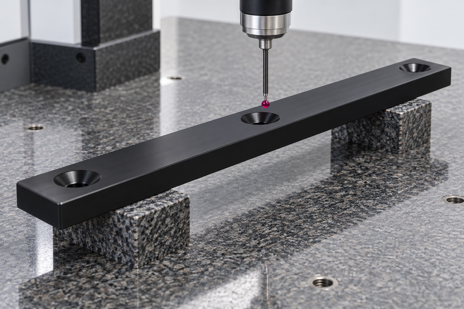
Prepare a drawing-linked first-part report
The report would identify drawing revision, material lot and numbered requirements, with inspection methods and support conditions. Relevant evidence would include the specified sliding-face relationship, mounting geometry and recess features. No numerical results are supplied because this representative example has no manufactured sample or inspection record. Material and dimensional evidence would support acceptance within the purchased component scope only. It would not establish friction, wear rate, debris generation, allowable drawer load or complete medical equipment safety without the responsible program's separate evaluation of the full contact and operating configuration.
Define an optional drawer travel trial
A limited trial could check seating, installation access and agreed clearances through the specified travel with identified components. The procedure would record strip revision, screws, mating surface, support and any approved lubrication. It would not be described as endurance or load qualification. Unexpected contact would be documented before changing the strip or its mount. An unrecorded hand adjustment would not establish the repeat-production baseline. Results from one setup would not automatically apply to another screw head, support spacing, lubricant or cleaning arrangement simply because the strip retained the same outside outline.
Package without bending or rubbing
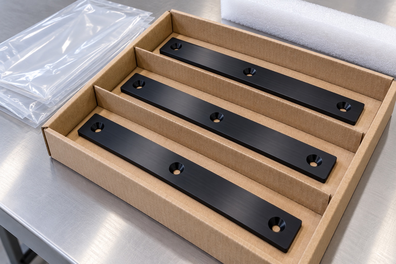
Transport packaging would support the strips and separate sliding faces from neighboring components. It would avoid bending pressure, contact with loose screws and unapproved adhesive residue. Any supplied drawer sample or hardware would retain clear identity and trial status where applicable. Ordinary bags would not imply sterile supply or a quantified cleanliness result. Grade, lot and revision information would accompany the shipment so the recipient could preserve the accepted configuration and distinguish it from a visually similar prototype, substituted polymer or strip manufactured for another drawer before entering controlled medical equipment assembly.
Retain the complete repeat-order baseline
The repeat-order record would preserve drawing revision, polymer grade, mating surface, support arrangement, approved screws, edge requirements, inspection method and packaging scope. Authorized prototype modifications would be incorporated explicitly. The equipment owner would review changed loads, contact materials, lubricants or cleaning conditions before reusing earlier observations. This representative example gives a structured purchase framework for a CNC wear strip: define contact, support the geometry and deliver traceable evidence. It keeps service life, friction performance, maintenance requirements and complete medical-device qualification separate from claims that a dimensional report and generic polymer name cannot substantiate alone.
Manufacturer background reference: www.ensingerplastics.com.
FAQ
Is this a delivered strip with a proven wear life?
No. It is a representative manufacturing example for a proposed component. No actual customer shipment, wear result, friction coefficient, allowable drawer load, achieved tolerance, certification or complete medical-device validation is asserted, and the illustrations are not inspection records.
What defines the recessed mounting holes?
Approved drawings and the actual fastener arrangement define their geometry and references. Head seating, remaining material and clearance to the sliding path must be reviewed together. A random screw that appears flush is not a complete production specification.
What would the first-part report show?
It would document agreed dimensions and geometry, material identity, methods, references and measurement condition. By itself it would not establish friction, abrasion life, particle generation, maintenance intervals or safe operation of the complete equipment drawer.
Can a strip be forced flat during inspection?
Only if that is the explicitly specified measurement condition. A required free-state result cannot be obtained by forcing the strip into shape. Define installed or loaded checks separately and record their acceptance meaning and support arrangement.
Can a drawer travel check be included?
Yes, with identified components, a written procedure and agreed seating, access and clearance checks. It remains separate from load and wear qualification unless those activities are independently specified, authorized and documented for the complete operating configuration.
Which changes require review before repeating manufacture?
Review polymer grade, screw geometry, support spacing, mating surface, lubrication, cleaning and operating conditions. Preserve controlled revisions and evidence rather than automatically extending earlier assembly or wear conclusions to a modified medical equipment drawer.

tanghangyun@oemach.com