
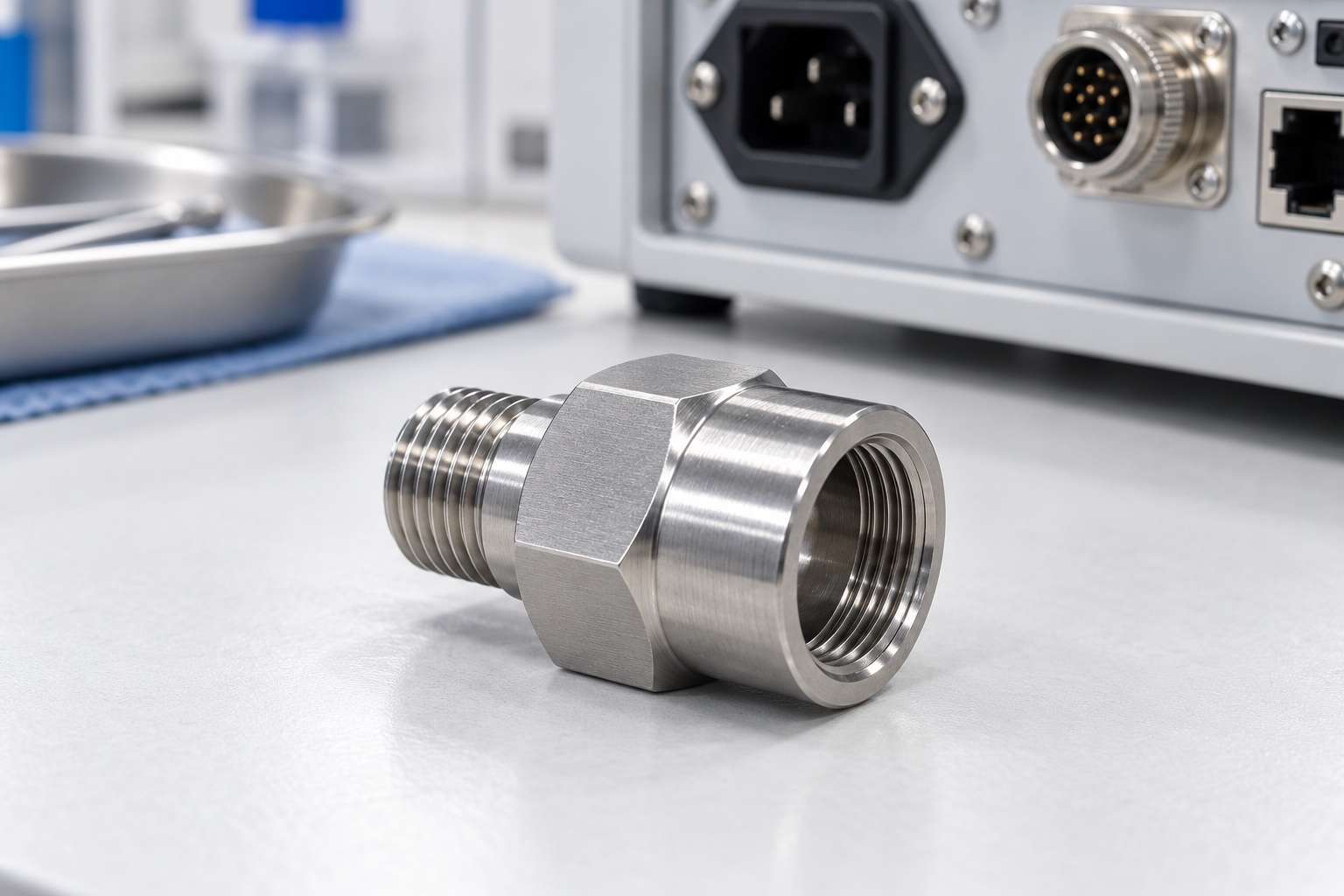
A representative proposed enclosure adapter
This example considers a proposed 316L stainless cable-gland adapter with an external threaded end, an internally threaded receiving end, wrench flats and a through passage for a medical equipment enclosure. It illustrates a possible manufacturing workflow, not an actual customer delivery or a qualified complete cable entry. Images show concepts rather than achieved dimensions or testing. Final thread designations, material condition and sealing arrangement would require approved project documents. No ingress rating, pull resistance, electrical performance, certification, achieved tolerance or validated medical-device performance is claimed for this proposed component.

Confirm both mating interfaces before planning
The proposed order would begin with controlled component documents and the approved gland, panel, seal and retention information. Both thread identities would be explicit, including applicable requirements and intended engagement. The supplier would not infer compatibility from a matching diameter or an unidentified sample. Questions about panel thickness, thread runout, internal access or sealing location would be returned for written clarification. The purchased scope would distinguish dimensional manufacture, an optional assembly trial and any separate ingress, electrical or equipment-level evaluation assigned to the responsible design program for the complete enclosure configuration.
Preserve stainless material and lot identity
Raw stock would be specified as the approved 316L material with the required condition and documentation. Material and lot information would remain linked to cut blanks and finished adapters. A visually similar stainless bar would not be accepted automatically as an equivalent. The supplier would review the stock form and machining allowance with the planned route. A proposed grade substitution would need authorization before production. The material designation would remain an input to the design rather than an unsupported guarantee of cleaning compatibility, universal corrosion resistance or medical certification of the complete cable-entry assembly.
Establish turning references for the interface
Initial turning would establish the passage and cylindrical references needed for the threaded ends and sealing contacts. Workholding would preserve the required relationships without damaging finished areas. The supplier would control chips and inspect access to internal features before committing to the route. Intermediate checks could confirm the sequence but would not replace final acceptance. If an additional setup were required, reference transfer would be documented. The objective would be repeatable finished geometry against the approved drawing rather than one sample that appeared correct when attached to a conveniently available shop fitting.

Produce the external threaded connection
The external end would follow the approved thread designation, engagement length, entry condition and any specified relief. Tooling and process choice would depend on the actual geometry and inspection requirements. The supplier would not change a thread family or lead-in informally because another fitting seemed easier to install. Any authorized alteration would enter the controlled drawing and acceptance plan. Thread protection during later operations would be considered in advance, and a successful partial mating with a sample would not replace the specified production inspection of the completed threaded interface.
Machine the internal thread and passage
The receiving thread and through passage would be produced with attention to access, internal steps and the cable's approved installation route. Thread runouts and hidden transitions would be reviewed before manufacture. Burr removal would preserve the specified geometry rather than enlarge the passage without authorization. The supplier would resolve model and drawing discrepancies before choosing a production detail. An approved connector or cable sample could support a defined trial, but its ability to pass through one adapter would not establish all thread, sealing or clearance requirements for repeat production.
Complete wrench flats and sealing contacts
Secondary machining would produce the approved wrenching features without losing the relationship to the turned interfaces. The route would protect finished threads and sealing faces from workholding damage. Contact widths, face geometry and any separate surface-texture requirement would follow the controlled drawing. A supplier would not choose a gasket arrangement from appearance. The review would consider installation-tool access near the actual panel and enclosure. Any needed geometry change would be authorized and reflected in inspection documents instead of being left in a manually fitted prototype or an informal workshop instruction.
Apply only the specified final process
If passivation or another treatment were required, documentation and final-condition checks would be agreed beforehand. Edge finishing would examine both passage ends, thread entries and internal transitions. Uncontrolled polishing would not conceal a sealing-face defect or thread problem. Markings would remain outside functional contacts unless approved. Cleaning would follow the purchased scope. The example does not infer chemical compatibility, corrosion behavior or quantified cleanliness from a shiny appearance. A changed treatment would be reviewed against the accepted material and interface configuration before being incorporated into production and repeat-order records.
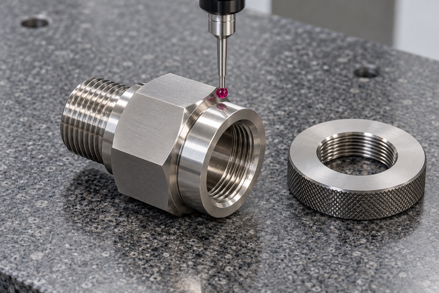
Create a drawing-linked first-part report
The report would identify the drawing revision, material lot and numbered requirements, including both specified threads, passage geometry and relevant sealing and mounting relationships. It would document methods, gauge identity and the agreed acceptance meaning of any mating trial. No numerical results are provided because this representative example has no manufactured sample or inspection record. Material and dimensional evidence would support acceptance within the purchased component scope only. It would not establish ingress protection, pull resistance, electromagnetic performance or electrical safety without separate approved evaluation of the complete gland, adapter, seal and enclosure installation.
Agree a limited installation trial
An optional procedure could check engagement, assembly-tool access and agreed cable clearances with identified approved components. It would record the adapter revision, gland, sealing elements, panel thickness and retention arrangement. Installation conditions would be supplied by the responsible design team rather than invented by the turning supplier. A hand-tight bench fit would not be described as an ingress or electrical qualification. If unexpected contact appeared, the team would document it before changing the adapter or seal. Results from one configuration would not automatically qualify a different gland, panel or installation method.
Protect exposed threads during shipment
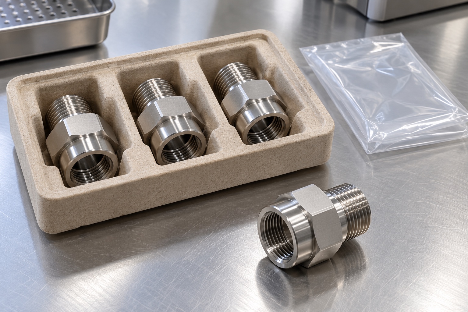
Packaging would separate adapters and shield threads, sealing contacts and passage entrances from impact and rubbing. Protective caps or supports, where approved, would not introduce uncontrolled residue into the passage. Separately supplied sealing elements and mating samples would retain clear identity and status. Ordinary transport bags would not imply sterile supply or a quantified cleanliness result. The revision, material lot and evidence package would remain associated with the shipment so receiving personnel could preserve the accepted configuration and distinguish a similar-looking but differently threaded adapter before installing it in the medical equipment enclosure.
Preserve the repeat-production configuration
The repeat-order package would retain the drawing revision, both thread designations, material condition, gland and panel documents, sealing arrangement, final process and inspection plan. Authorized prototype changes would be incorporated explicitly. The equipment owner would review altered seals, retention, wall thickness or installation procedures before reusing earlier conclusions. This representative example offers a structured way to purchase a machined cable-entry adapter: define each interface, protect functional surfaces and provide traceable evidence. It keeps enclosure protection, strain relief, electrical behavior and complete device qualification separate from claims that a turned stainless component and dimensional report cannot establish alone.
Manufacturer background reference: www.lapp.com.
FAQ
Is this a delivered adapter with an ingress rating?
No. It is a representative CNC turning example for a proposed component. No actual customer shipment, ingress rating, pull resistance, achieved tolerance, certification or complete medical-device validation is asserted, and the images are illustrative concepts rather than qualification records.
What defines the two threaded ends?
Approved component and mating-interface documents define their thread identities, applicable requirements and engagement. Similar appearance or a sample fitting that starts to screw in is not a complete specification or evidence of production interchangeability.
What would the first-part report demonstrate?
It would document agreed drawing characteristics, references, material evidence and inspection methods for the adapter. By itself it would not establish the protection, retention or electrical performance of a complete installed cable-entry assembly.
Can a supplier select a seal or tightening torque?
Only as part of an explicitly approved design scope. Otherwise the responsible equipment team must define the sealing arrangement and installation procedure. A material name and thread size do not supply a universal gasket choice or torque.
Can an installation trial be purchased?
Yes, with identified components, a written procedure and explicit engagement, access and clearance checks. It remains separate from ingress, pull-resistance and electrical qualification unless those activities are independently specified, authorized and documented for the complete configuration.
Which changes require review before repeating manufacture?
Review thread identities, gland, seals, panel thickness, retention, installation procedure, material and final process. Preserve approved revisions and evidence rather than automatically transferring earlier assembly or qualification conclusions to an altered cable-entry arrangement.

tanghangyun@oemach.com