
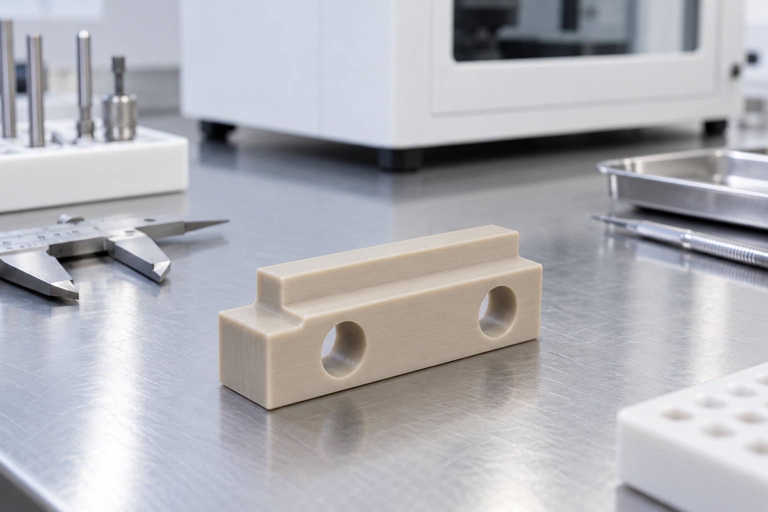
A proposed equipment-side spacer
This representative example considers a natural-color PEEK spacer block with two mounting holes, flat contact faces and a locating shoulder for a medical instrument assembly. It illustrates a possible CNC manufacturing plan, not a delivered customer project, certified insulation component or validated medical device. Images are illustrative concepts rather than measurement or qualification records. Final geometry, grade and acceptance conditions would require approved project documents. No insulation rating, allowable load, clinical suitability, certification or achieved tolerance is claimed without the application-specific evidence needed to support those statements within the complete equipment configuration.

Review the stack and mounting arrangement
The proposed order would begin with the approved component drawing, model, contact arrangement and mounting hardware information. The review would identify which faces establish separation and which shoulder or hole features position mating parts. Overall block thickness would not be treated as a complete stack-height specification. A sample assembly could support discussion only if identified and authorized. Missing requirements would be clarified before the cost estimate and manufacturing route were finalized. The purchase scope would distinguish dimensional manufacture, an optional mechanical fit trial and any separate electrical or equipment-level qualification responsibility.
Preserve the approved material grade
The raw material order would specify the required PEEK grade, form and traceability documents. Natural color would not be accepted as proof of identity. Grade and lot information would remain associated with the blanks through machining, finishing and packaging. A proposed substitution would require review before use, even if it appeared mechanically similar. The supplier would not transfer a typical datasheet property into a claimed performance result for the spacer. Material suitability would remain an application decision, while the manufacturing scope would preserve the approved identity and produce the geometry and evidence defined by the controlled drawing.
Establish supported reference faces
The early machining route would establish the contact and reference surfaces needed for later operations. Workholding would avoid excessive pressure that could distort the part while producing an apparently correct dimension. Chips or polymer debris at setup contacts would be controlled before each reference transfer. Intermediate checks could help confirm the route but would not replace final acceptance. If material removal around the shoulder affected released geometry, the supplier would review the process rather than compensate through undocumented clamping force. The intended result would be a repeatable spacer, not one sample made acceptable only while restrained.
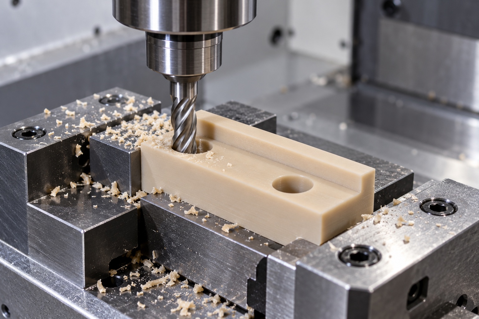
Machine the controlled stack-height features
The contact faces and step would be machined according to their approved relationship, rather than as unrelated outside dimensions. The route would distinguish the main block thickness from any shoulder height that establishes a second interface. Tool access and internal transitions would be reviewed before production so an unavoidable radius did not become an unexpected assembly interference. Any proposed relief would need authorization. The supplier would not remove material informally to match an unapproved mating sample, and the drawing revision would remain the acceptance basis for both the first component and subsequent production.
Produce holes relative to functional references
The two mounting holes and any specified counterbores would be produced in relation to the controlled contact faces and shoulder. Their role would depend on the approved fastening arrangement, including screw-head or washer contact and assembly-tool access. A clearance diameter alone would not define the complete installation condition. The supplier would resolve discrepancies between model and drawing before making production decisions. An authorized change to a hole or shoulder would be documented and reflected in inspection, rather than left as an unrecorded adjustment that made one trial assembly seem easier to install.
Control polymer edge finishing
The finishing process would examine hole exits, shoulder transitions and contact-face edges for attached material. Removal would remain within drawing limits and preserve the specified geometry. Uncontrolled scraping, heat smoothing or solvent treatment would not be introduced simply to improve appearance or fit. Any cleaning step would follow the documented material and purchase requirements. A glossy surface would not establish a verified texture, electrical condition or cleanliness level. A damaged reference face would be treated as a component issue rather than hidden by presenting a neatly packaged part or a successful hand-fitted demonstration.
Agree the measurement condition
The inspection plan would state the support arrangement, references and any environmental conditioning needed for the polymer part. Measurement force would be appropriate to avoid deforming the geometry being evaluated. Contact-face relationships and accessible hole features could need different methods. The supplier would resolve inaccessible or ambiguous measurements before production. A thickness check performed under excessive pressure would not be presented as the unloaded component's accepted size. If the drawing required an installed-condition check, that arrangement would be separately defined instead of silently replacing a free-condition requirement or extending an unloaded result to an assembled load case.
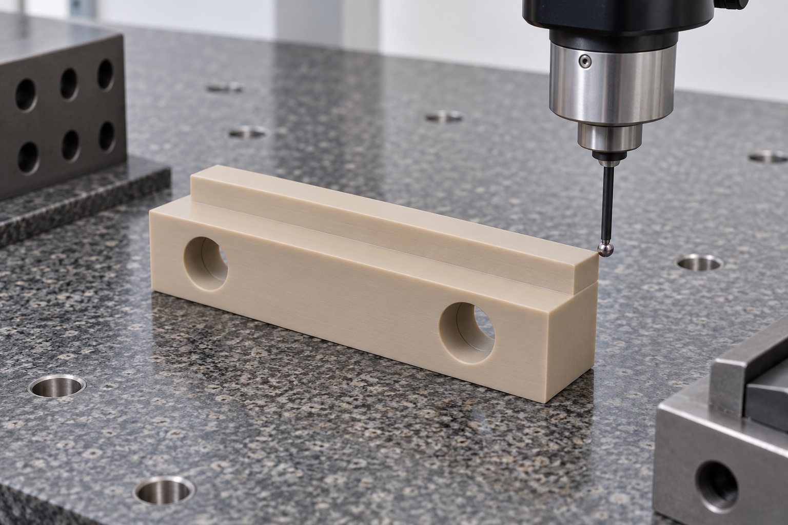
Prepare traceable first-part evidence
The first-part report would identify the drawing revision, material lot and numbered requirements, including relevant stack heights, shoulder relationships and mounting geometry. It would record the agreed measurement condition and any defined gauge. No numerical results are supplied because this example has no manufactured specimen or inspection record. Grade documents and dimensional evidence would support acceptance within the purchased component scope. They would not establish electrical insulation compliance, long-term assembly behavior or medical-device safety. Those conclusions require the responsible equipment program's own approved evaluation of the complete configuration and its actual operating environment.
Define an optional mechanical trial
An optional trial could check seating, hardware access and agreed clearances using identified approved mating parts. Its procedure would state spacer revision, grade and assembly configuration. The result would not be described as electrical or device-level qualification. If an unexpected contact appeared, the team would document it before changing the spacer or mating component. A hand-fitted specimen would not become the production standard without approved documents and corresponding inspection criteria. Results from one hardware arrangement would not automatically apply to another screw, washer, grade or installation, even if the block's outline remained broadly similar.
Protect contact faces during delivery
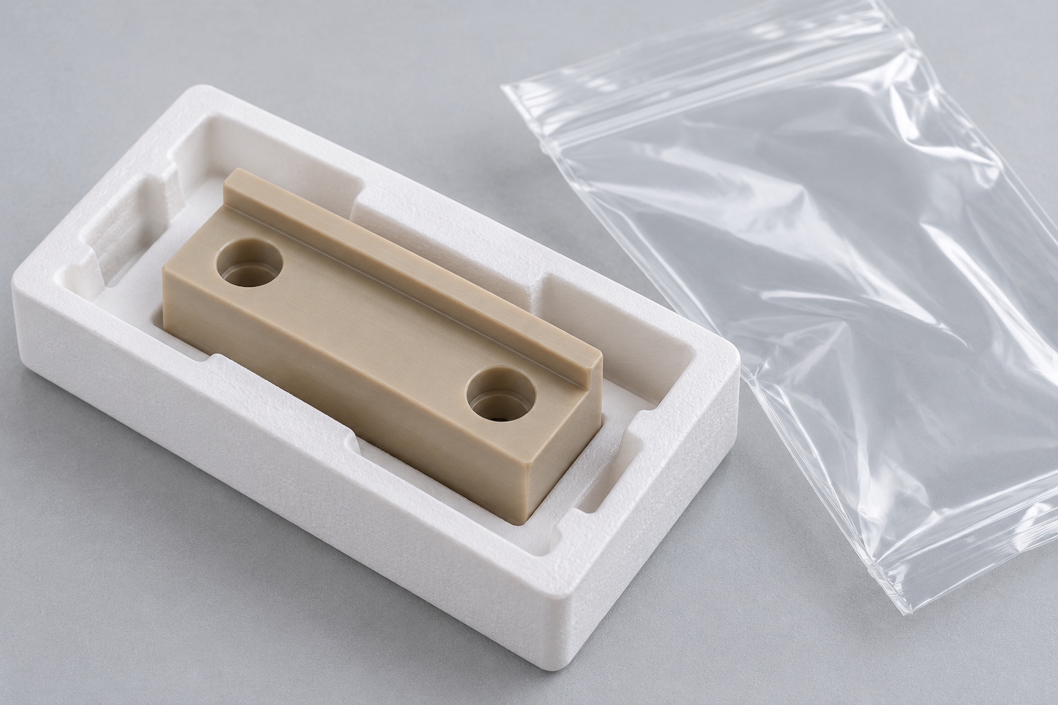
Packaging would separate spacers and protect shoulders and contact surfaces from rubbing, loose debris and unauthorized marking. Identification would remain with the lot rather than introduce labels into functional contact areas. The cleaning scope would be described accurately; ordinary transport bags would not imply sterile supply or a quantified cleanliness result. Any purchased cleanliness criterion would have a stated verification method. The recipient should be able to distinguish the accepted grade and revision from visually similar polymer parts and retain any assembly samples as identified trial items rather than treating them as qualified production equipment.
Maintain the complete repeat-order baseline
The repeat-order record would retain the drawing revision, grade, raw material requirements, mounting arrangement, inspection method and packaging scope. Authorized prototype modifications would be incorporated explicitly into controlled documents. The equipment owner would review changed hardware, environment or material before transferring prior conclusions. This representative example provides a structured way to purchase a CNC spacer for medical instrumentation: define the functional stack, preserve material identity and verify agreed geometry, while keeping insulation, load behavior and medical-device qualification separate from claims that cannot be supported by a component drawing and an unloaded dimensional report alone.
Manufacturer background reference: www.victrex.com.
FAQ
Is this a delivered or electrically qualified component?
No. It is a representative CNC manufacturing example. No actual shipment, insulation rating, achieved tolerance, certification or complete medical-device validation is asserted, and the illustrations are not production or qualification evidence.
What establishes the purchased material?
The order should identify the approved PEEK grade, raw material form and required documentation. Natural color is not proof of identity, and any substitute requires review before it enters production.
What would the first-part report cover?
It would cover the agreed drawing requirements, including relevant stack heights, shoulder relationships and mounting geometry, together with the specified measurement condition. It would not by itself qualify electrical or equipment-level performance.
Can the block be hand fitted to an assembly sample?
Only within an approved process and drawing limits. A geometry change requires authorization, controlled documentation and appropriate inspection before it becomes the repeat-production baseline rather than an unrecorded prototype adjustment.
Can a mechanical seating trial be included?
Yes, with identified components and explicitly defined checks. It remains separate from electrical, long-term load and device-level qualification unless those activities are independently specified, authorized and documented.
What must remain controlled for repeat manufacture?
Retain revision, grade, raw material evidence, mounting arrangement and inspection plan. Review changed hardware, environment or material before assuming earlier assembly or qualification conclusions remain valid for the repeated order.

tanghangyun@oemach.com