
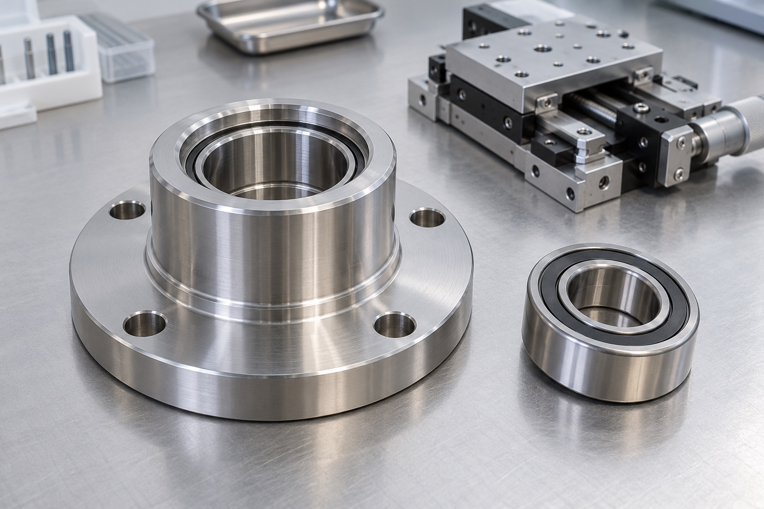
A representative flanged housing
This case presents a proposed CNC route for a 316L stainless steel bearing cartridge used in a laboratory positioning stage. The concept has a mounting flange, an external locating region, an internal bearing seat and an axial abutment. It is a representative manufacturing example, not a named customer's delivery or a claim of measured stage performance. The bearing arrangement and equipment design remain the customer's engineering responsibility. The supplier's work begins with a released drawing that makes the material condition, fit, geometry and required evidence clear enough to manufacture and inspect.

Review the bearing and mounting references
The inquiry should identify the approved bearing, the cartridge's installed orientation and the features that locate it in the frame. Check whether the bearing is retained by a cover, ring or another defined component. A model that shows a cylindrical recess does not establish a fit, an axial requirement or a preload arrangement. Resolve missing notes before planning the finish bore. Record the purpose and identity of any mating samples. A sample bearing can support a separately agreed trial, but its presence should not silently replace the released dimensions and acceptance conditions.
Retain material identity from the blank
Confirm 316L and its ordered stock condition, blank form and certificate requirements. Preserve the heat or lot reference through cutting and work in progress so it can be connected to delivery documentation. Allow material for the flange, locating region, seat and any subsequent operation. Do not assume that all visually similar stainless stock is equivalent. This case makes no general claim of medical certification or compatibility with every cleaning agent. Any contact classification, special treatment or material assessment must be supplied as a defined order requirement rather than inferred from the alloy designation.
Establish a route around the functional references
One possible plan creates a controlled external reference and flange face before finishing the bore and axial abutment. Review tool access and the remaining support throughout that sequence. The actual drawing may justify another order of operations, so the route must be evaluated rather than treated as a universal recipe. Identify which features establish the machining axis and which simply provide grip. Avoid finishing a critical seat from a setup that cannot preserve its specified relationship to the mounting interface. Document the program and setup references used for the first article.
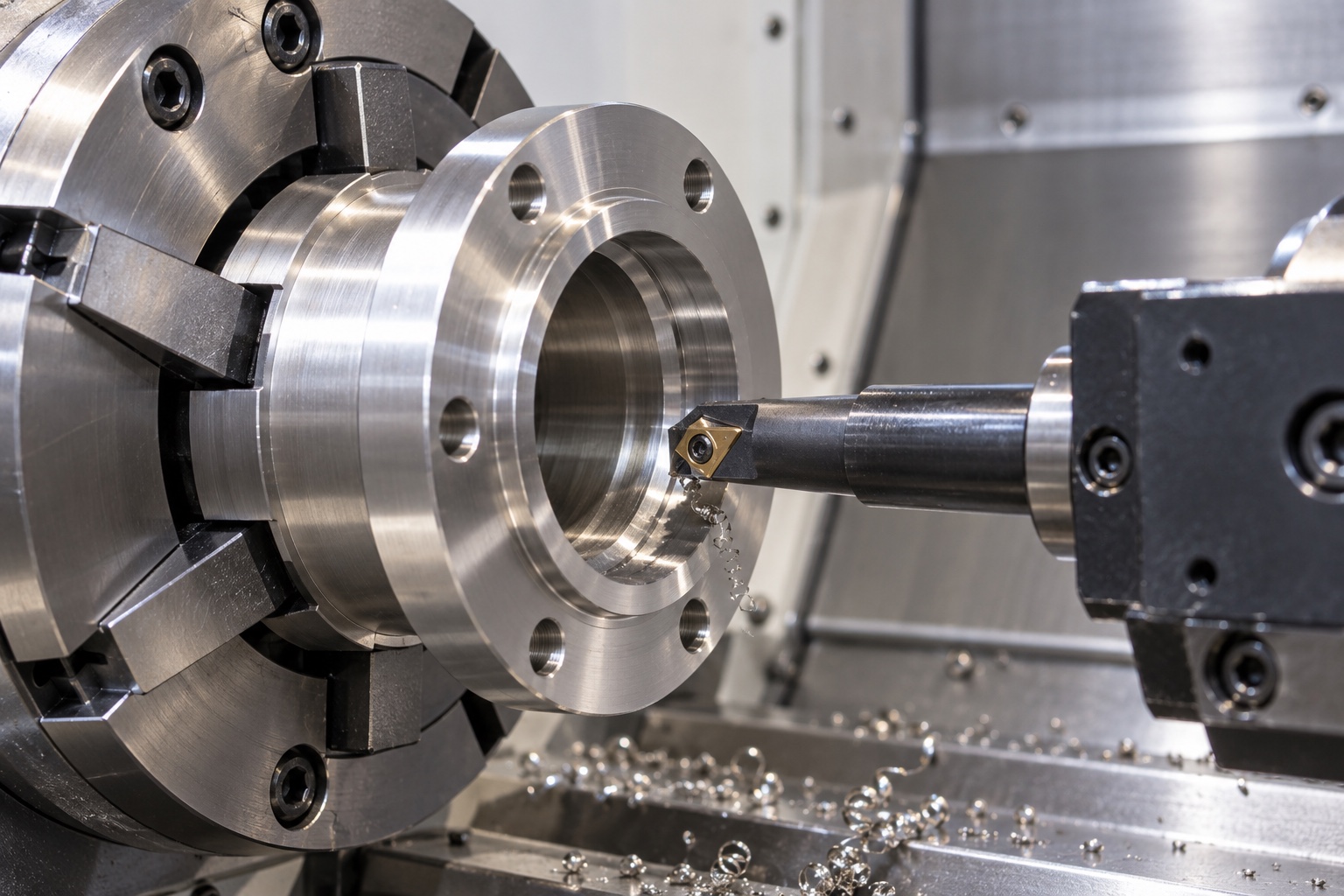
Control support as the wall becomes thinner
The cartridge's stiffness changes as the internal material is removed. Review collet or jaw contact, unsupported length and the flange's response to clamping. A bore measured while the component is compressed may not describe the free part. Establish a released-state check at a useful point in the route and verify final acceptance in the condition required by the drawing. If a support strategy changes after the first article, review the affected characteristics rather than treating it as a purely operational adjustment. The repeat route should retain the evidence needed to explain the accepted condition.
Finish the seat and axial abutment together
Plan the bore and shoulder as related features, not independent dimensions that happen to share a cavity. Review boring-bar reach, chip evacuation, the intended usable seat and the specified corner clearance. A correct diameter does not prove that a bearing reaches the proper axial support. Compare the shoulder and relief geometry with the approved bearing interface, and clarify any inaccessible feature. Do not enlarge a corner relief or shorten the seat merely to suit an available cutter. Any change that affects the released interface needs an authorized engineering disposition.
Transfer the mounting pattern deliberately
Where flange holes or other features require a second setup, locate the part using the approved references and preserve the required relationship to the bearing seat. Document what constrains rotation and what establishes axial position. A repeatable fixture is useful, but it does not remove the need to inspect the relationship it is intended to produce. Review access for the drill, finishing tools and inspection probe. Mounting-hole burrs must be removed without damaging the flange face or pushing loose material into the finished bore. Check the part after the operations that could affect those surfaces.
Complete edge control and specified treatment
The seat entry, retention features, mounting holes and shoulder can have different edge requirements. Use controlled finishing that removes attached material while preserving the intended support and engagement. Where passivation or another treatment is ordered, follow the defined material-compatible process and retain the requested documentation. Verify relevant features afterward when the order requires finished-condition dimensions. A treatment record does not establish bearing fit or sterile delivery. Keep handling marks, residue and dimensional acceptance as separate observations so a visually attractive component is not mistaken for a completely verified one.
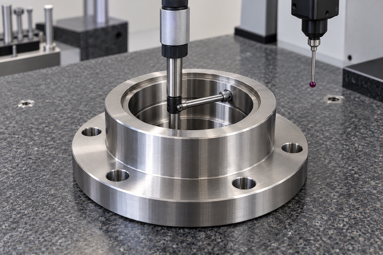
Build a traceable first-article inspection package
The proposed report records material and drawing identity, seat size, the specified geometric characteristics, abutment location, locating interface, flange dimensions and mounting pattern. Use methods appropriate to the required feature and access, with the support condition stated. Record limitations rather than accepting a characteristic that the chosen method cannot establish. Link each result to the drawing so a later deviation can be investigated precisely. This case includes no invented numerical inspection results. Actual values and approval must come from the manufactured first article, the agreed equipment and the released acceptance requirements.
Define any bearing assembly trial separately
A customer may request a trial with approved bearings, shaft and retention hardware. Agree the installation method, mounting condition and required observations in advance. Engagement, seating, rotating torque and running accuracy are different checks. This case does not assert that a dimensional report proves preload or stage-positioning performance. Nor does it invent a tightening value for the customer's assembly. If a trial shows a problem, retain its configuration and result before deciding whether the seat, another component or the assembly procedure needs attention. Keep component acceptance and system approval clearly distinguishable.
Protect the finished bearing interface
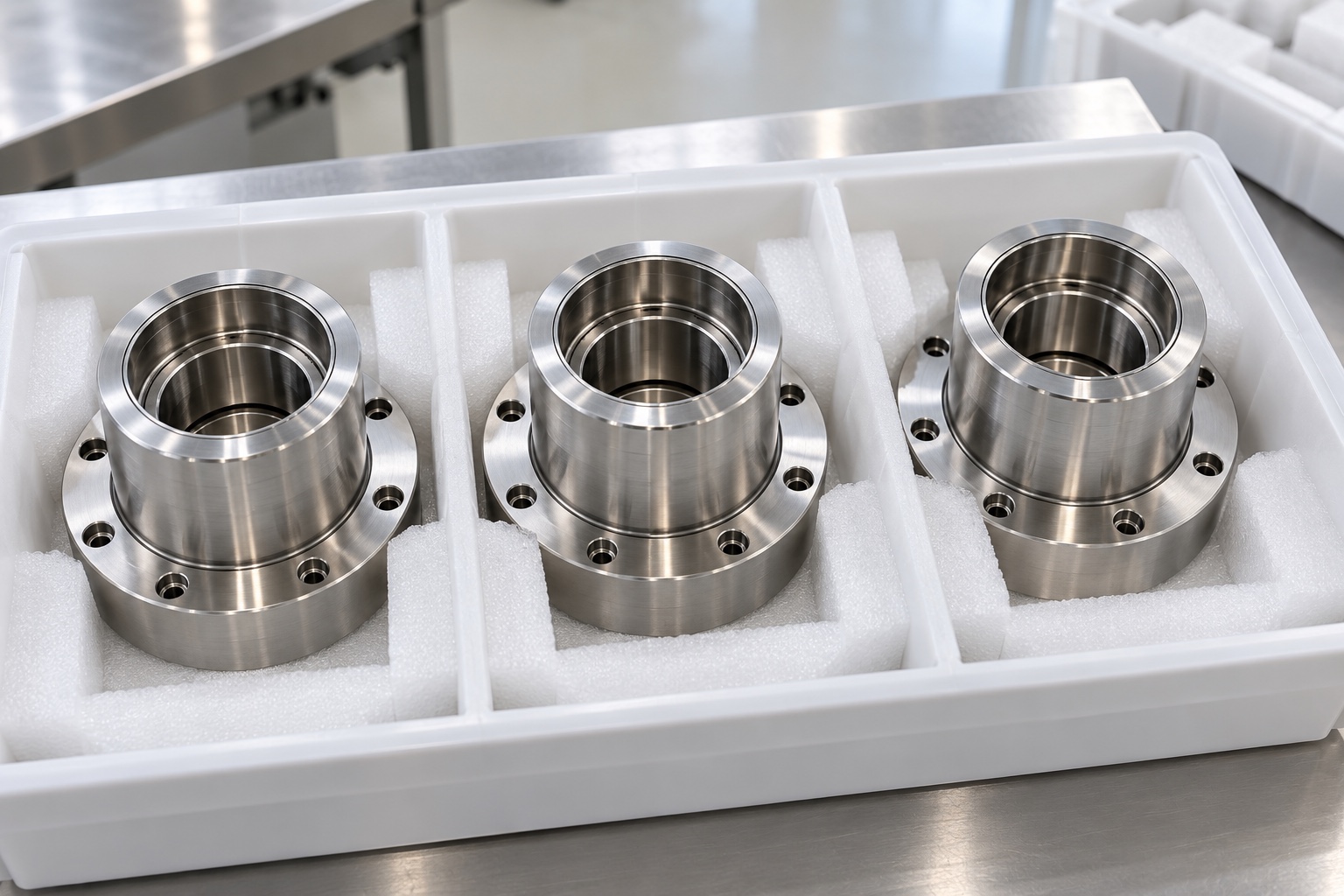
Use the ordered cleaning and drying process to remove relevant machining and treatment residues. Handle the seat and shoulder so they do not contact other metal parts or abrasive packaging. A compatible cap or separator may be useful, but it must not damage the entry or introduce debris. Label the packaging with part number, revision, lot and quantity. State the actual condition delivered without implying a sterile barrier or an unverified particle limit. The receiving team should be able to match the protected component to its material and inspection records before assembly.
Prepare the controlled repeat build
Repeat production should preserve the accepted drawing and model, material condition, finish, inspection plan, first-article disposition and any authorized deviations. Review changes to the bearing reference, mounting interface, tools, workholding or treatment for their effect on accepted geometry. A useful RFQ also states prototype and repeat quantities, packaging and any separately priced assembly trial. This representative example promises neither a universal tolerance nor a price or delivery time. Those commitments require review of the actual part and verification work. The goal is a repeatable, documented component, not a claim that the complete medical instrument has been validated.
Manufacturer background reference: www.skf.com.
FAQ
Is this a documented customer delivery?
No. It is a representative component and manufacturing route without a named customer, shipment or measured running result. A real project needs its own controlled interface, acceptance records and delivery evidence.
Does choosing 316L determine the bearing fit?
No. The equipment team must define the fit using the actual bearing arrangement and operating requirements. Material identity is one input, not a substitute for the released dimensional and geometric specification.
Which features share the functional reference?
The drawing determines the relationship between the bearing seat, abutment, external locator, flange and mounting pattern. The route and inspection plan should preserve and verify those relationships rather than assume that every visible cylinder is a datum.
What is checked after final treatment?
Check the finished-condition features and surface observations required by the order, retaining the treatment documentation. Relevant dimensions should not be inferred from pre-treatment readings or from the uniform appearance of the completed part.
Can a bearing trial be included?
Yes, as separately defined work using approved mating parts, installation and acceptance conditions. A hand-fit observation is not interchangeable with a preload, torque or running-accuracy test, and this example claims none of those results.
What should a repeat order preserve?
Preserve the drawing and model revisions, exact material, finish, bearing references, accepted first article, inspection conditions and packaging requirements. Review changes that can affect geometry or assembly rather than relying on the previous part's photograph.

tanghangyun@oemach.com