
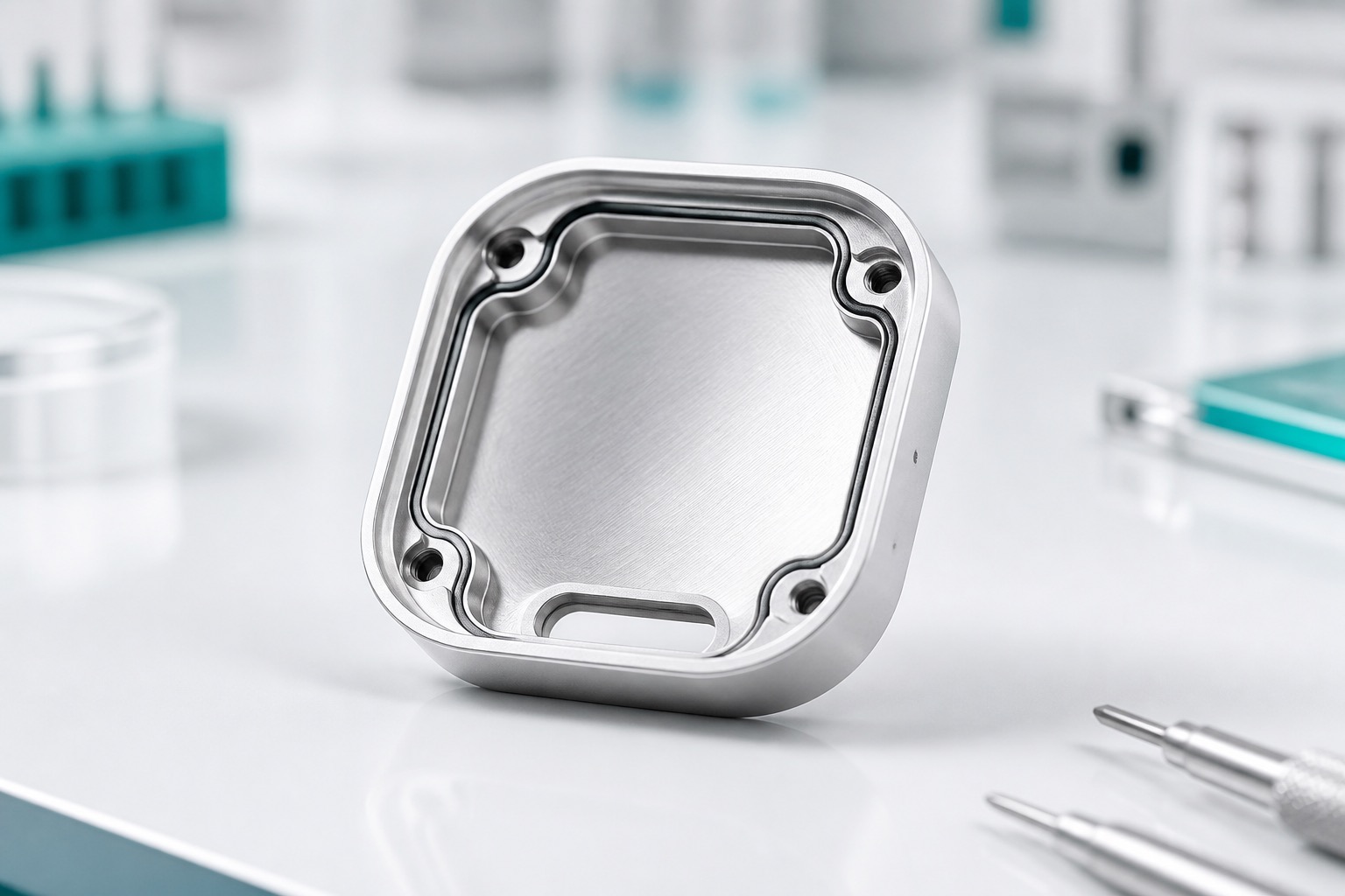
6061-T6 Wearable Patient Monitor Rear Cover: Precision CNC Machining Case
Representative application
This case describes a representative 6061-T6 rear cover for a wearable patient monitoring module. The cover includes thin walls, a gasket groove, sensor-window references, small fastener holes and a cosmetic exterior surface. It is a manufacturing example rather than a claim about a certified device. The device manufacturer controls patient-contact assessment, electronics sealing, cleaning instructions and final validation; the machining supplier controls material, CNC process, finish coordination, inspection and delivery records.

Released package review
The controlled package includes a 2D drawing, 3D model, revision history, material grade, anodizing specification, masking map and critical-characteristic list. Before quoting, the shop reviews wall thickness, cutter access, burr-removal access, sensor-window location, gasket compression features and cosmetic zones. Missing information such as mating gasket size, screw torque target or color standard is returned for clarification before the first article.
Material and blank preparation
Certified 6061-T6 stock is selected with enough allowance for stable roughing and final cleanup. Material identity remains linked to the traveler from cutting through shipment. The blank is held to support thin walls without crushing them. Roughing removes internal pocket material in balanced stages, leaving stock on seal lands, sensor references and exterior surfaces for controlled finishing.
CNC machining sequence
The first setup establishes primary datums and roughs the main pocket. Later operations finish the gasket groove, sensor-window references, screw holes and cosmetic edges from controlled coordinates. Small cutters are monitored closely because wear can change groove width or leave raised burrs. After unclamping, the cover is inspected in the free state so distortion or spring-back is visible before finishing.
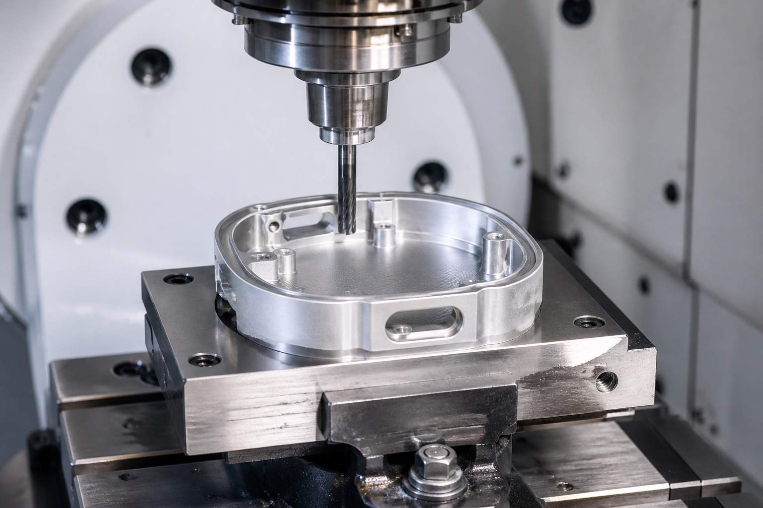
Anodizing and post-finish checks
If anodizing is specified, masking and thickness allowances are confirmed before production. Functional grooves and fitted features may need post-finish measurement because coating buildup can alter dimensions. Cosmetic color is judged to the agreed standard, while scratches or buildup on seal lands are evaluated as functional issues. Finish lot data stays tied to material and machining records.
Inspection and documentation
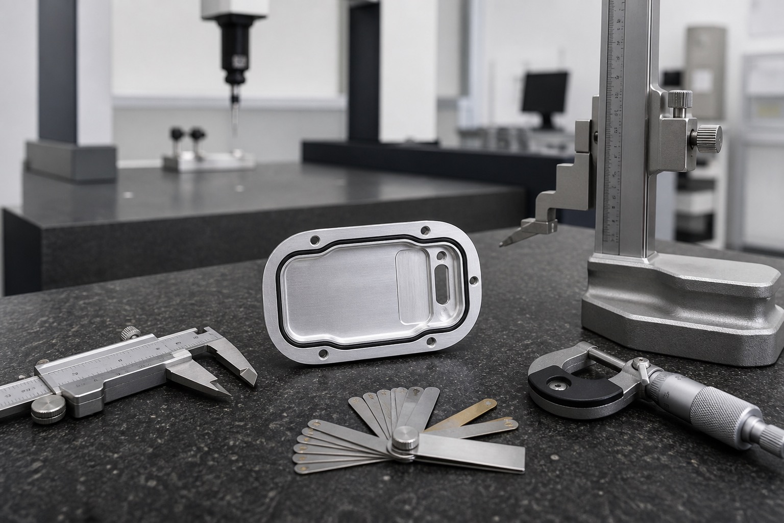
The first-article package can include material certificates, dimensional report, groove measurements, sensor-window position, flatness data, thread checks, finish records and representative photos. Optical tools may be used for small windows and grooves, while CMM or fixtures verify datum relationships. The inspection method should match the released drawing rather than relying only on visual comparison.
Cleaning and packaging
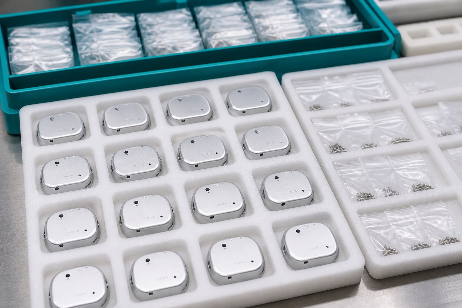
Each cover is cleaned to remove coolant, chips, anodizing residue and loose particles from pockets and holes. Finished parts are separated in trays or bags so cosmetic surfaces and seal grooves cannot rub. Labels identify part number, revision, material lot, finish lot and inspection status. The packaging is clean and protective, but it is not described as sterile unless a validated sterile route is specified.
Repeat production controls
For repeat orders, the controlled process includes CNC program, fixture, tool-life limits, deburring method, anodizing route, inspection plan, cleaning process and packaging specification. Trend checks on groove depth, window position and cover flatness can reveal drift before assembly yield drops. Any change to gasket design, coating, sensor stack or screw pattern should trigger review.
Customer handoff
The handoff defines approved first-article results, batch quantity, documentation package, cosmetic criteria and any customer-supplied assembly or environmental test. A stable forecast helps reserve matching material and finishing capacity. A complete revision package prevents obsolete sensor-window geometry or gasket details from reaching production.
FAQ
Is this a certified wearable medical device?
It is a representative machining case. Device certification, patient-contact assessment and system validation belong to the device manufacturer.
Why use 6061-T6 aluminum?
It offers useful weight, machinability and anodizing behavior, but the final alloy and finish must be approved by the device designer.
What controls gasket performance?
Groove depth, width, radius, seal-land flatness, screw pattern and mating gasket design together control compression.
Can anodizing change the fit?
Yes. Coating buildup can affect grooves and fitted details, so masking, allowance and post-finish inspection are planned.
How are cosmetic surfaces protected?
Parts are separated after finishing and packed so visible surfaces, seal grooves and sensor-window edges cannot rub.
What records can accompany the covers?
Material certificates, first-article reports, dimensional data, finish records, traceability and agreed inspection photos can be supplied.