
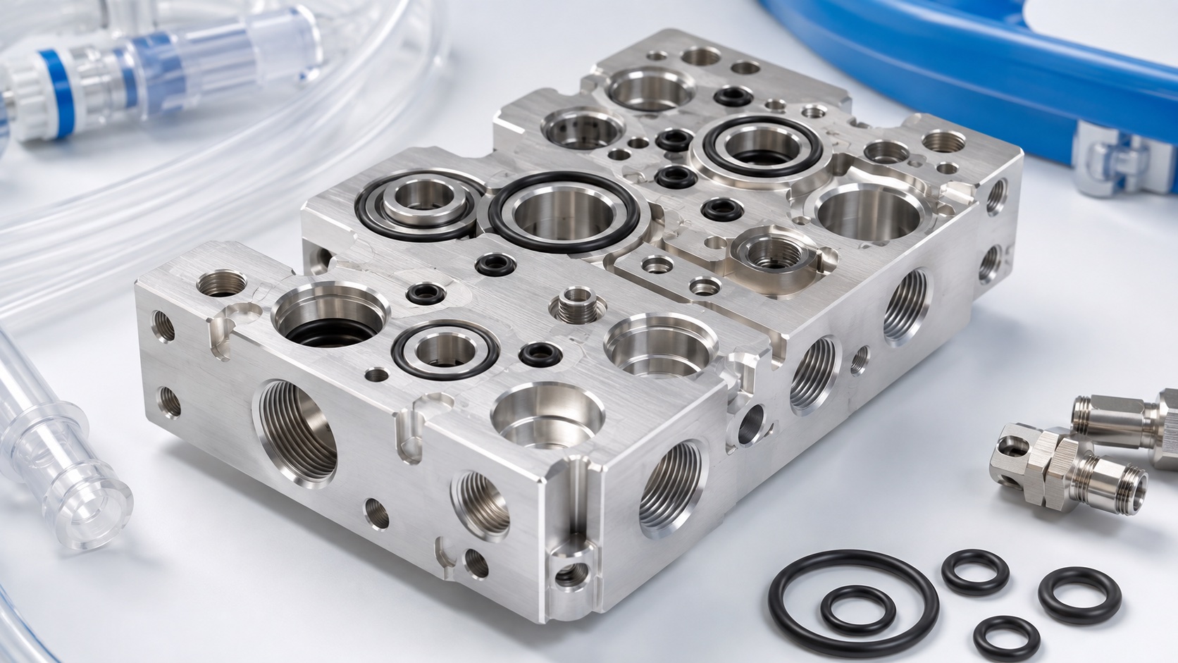
6061-T6 Anesthesia Flow-Sensor Housing: Precision CNC Machining Case
Representative application
This case describes a representative 6061-T6 housing used around a flow-sensing module in an anesthesia workstation gas-control subsystem. The component supports a main gas passage, a sensor pocket, pressure or sampling ports, gasket interfaces and mounting features. It is a machining case, not a claim about a certified medical device or a specific customer shipment. The equipment manufacturer controls the final pneumatic design, calibration and validation. The supplier controls material identity, CNC process, inspection evidence, cleaning and protected delivery of the released part.

Released manufacturing package
The released package includes a controlled 2D drawing, matching 3D model, revision history, critical-characteristic list and any finish or masking map. The drawing identifies the primary mounting face, side datum, bore axis, gasket land, port locations and threaded features. Before quoting, the shop reviews wall thickness near cross-holes, cutter access, burr-removal access, coating allowance, fixture contact zones and whether each critical surface remains measurable after finishing. Missing test limits or cleaning classes are returned to the customer for clarification.
Material and blank strategy
Certified 6061-T6 stock is selected with enough allowance for datums, pockets and finish cleanup. The lot number remains linked to the traveler through machining, finishing and shipment. Roughing removes material in balanced stages so the bore boss and gasket face are not pulled out of position by local stress. If anodizing is required, fitted surfaces and electrical or thermal contacts are reviewed before the first article. Any substitution of alloy, temper or finish is handled as a customer-approved change because it can affect assembly fit and validation.
CNC setup and machining
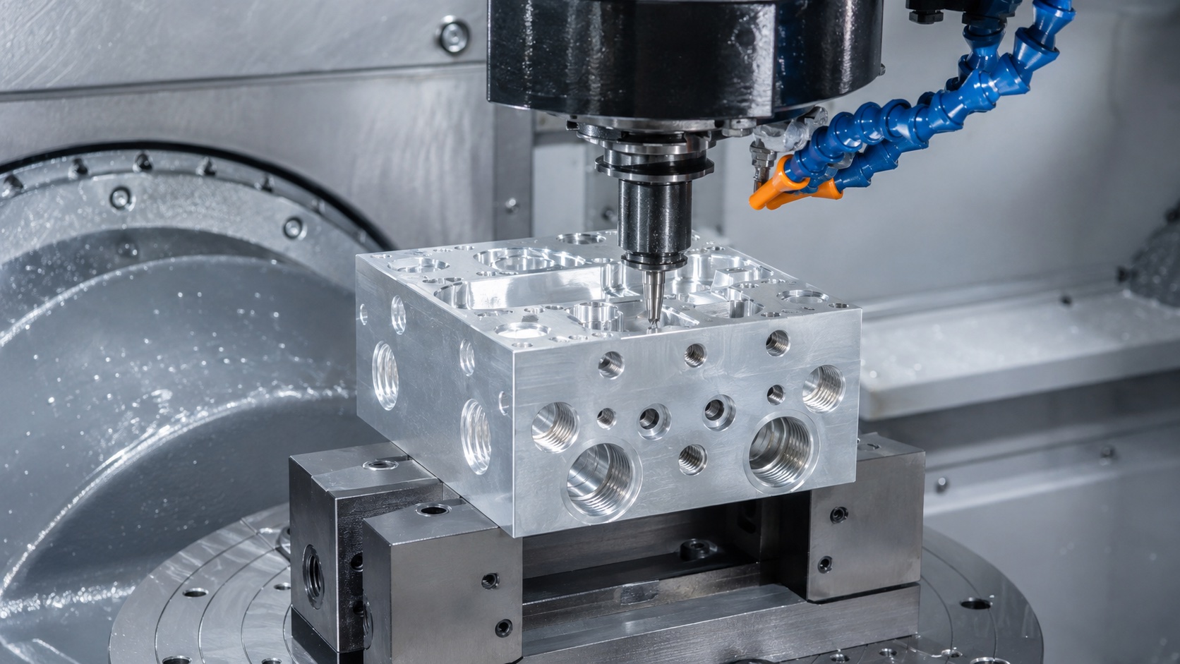
The first setup establishes the mounting datum and roughs the outside envelope. Subsequent operations open the gas passage, machine the sensor pocket, drill pressure taps and create threaded or dowel features from the same functional coordinate system. Precision bore finishing is left until the part is stable and the fixture supports the surrounding wall without distortion. Tool paths are chosen to reduce exit burrs at cross-holes, and tool-life limits are monitored on the small features. Setup changes are recorded so first-article results can be traced to the correct program and fixture revision.
Bore and sealing interface control
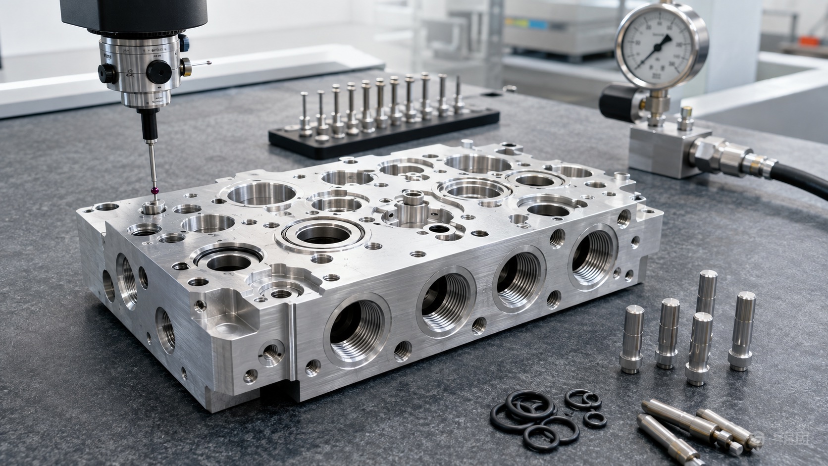
The sensor bore, nearby ports and O-ring groove are inspected as a related group. Bore size is checked with the drawing-defined method, position is related to the functional datums, and the groove is checked for depth, width and surface condition. Gasket lands are protected during handling because a small dent can create a leak path even when the bore measures correctly. If coating is applied, the inspection plan states whether the bore is masked, measured after finishing or completed with an approved post-finish process.
Deburring, cleaning and inspection records
Gas-path edges receive controlled deburring rather than casual polishing. Cross-hole intersections, thread starts and port exits are examined under magnification or by borescope when direct line of sight is limited. Cleaning removes chips, coolant and loose particles from the main passage and small ports. The first-article packet may include material certificates, dimensional report, photos of critical edges, finish inspection and cleaning confirmation. These records support the device manufacturer's validation work but do not replace it.
Functional test boundary
A leak or flow check can be added when the customer supplies a defined test specification. The required medium, pressure or flow condition, dwell time, port-blocking pattern, fixture interface, temperature condition and acceptance value must come from the device owner. Testing the bare housing is different from testing a complete sensor assembly, so the acceptance record identifies the actual state of the part. Results are kept with the lot and drawing revision, and any deviation is processed through the customer's approved method.
Packaging and repeat production
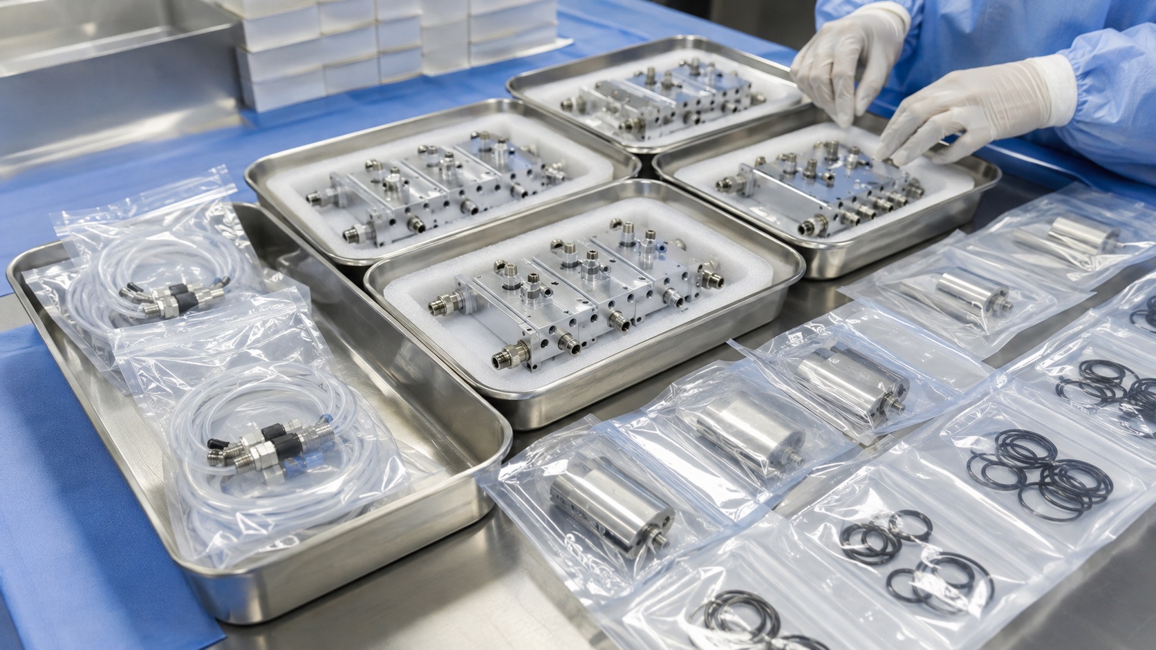
Finished parts are separated in clean trays or individual protective packaging so the bore, gasket land and threads cannot be damaged in transit. Labels identify part number, revision, material lot, finish lot and inspection status. For repeat production, CNC program revision, fixture revision, tool-life limits, coating map, cleaning method and inspection plan remain under change control. Trend data for bore position, groove depth and flatness can reveal drift before assembly yield is affected. Forecasts and batch sizes help reserve compatible material and finishing capacity.
FAQ
Is this a certified anesthesia device component?
It is a representative manufacturing case. Final medical-device certification and system validation belong to the anesthesia equipment manufacturer.
Why use 6061-T6 aluminum?
It offers low mass and good machinability, but the device designer must confirm gas compatibility, finish, grounding and cleaning requirements.
Which inspection data is most useful?
Bore size and position, groove dimensions, gasket-land flatness, port locations, thread quality, burr condition and finish state are commonly useful.
Can anodizing affect the bore?
Yes. Coating can change fitted dimensions, so masking, post-finish control or final-condition measurement should be defined on the drawing.
Can the supplier choose leak-test pressure?
No. Test medium, pressure, time, plugged ports and acceptance limits are defined by the device owner.
How are parts protected for delivery?
Critical bores, seal lands and threads are protected with clean packaging, separated parts and labels tied to lot, revision and inspection status.