
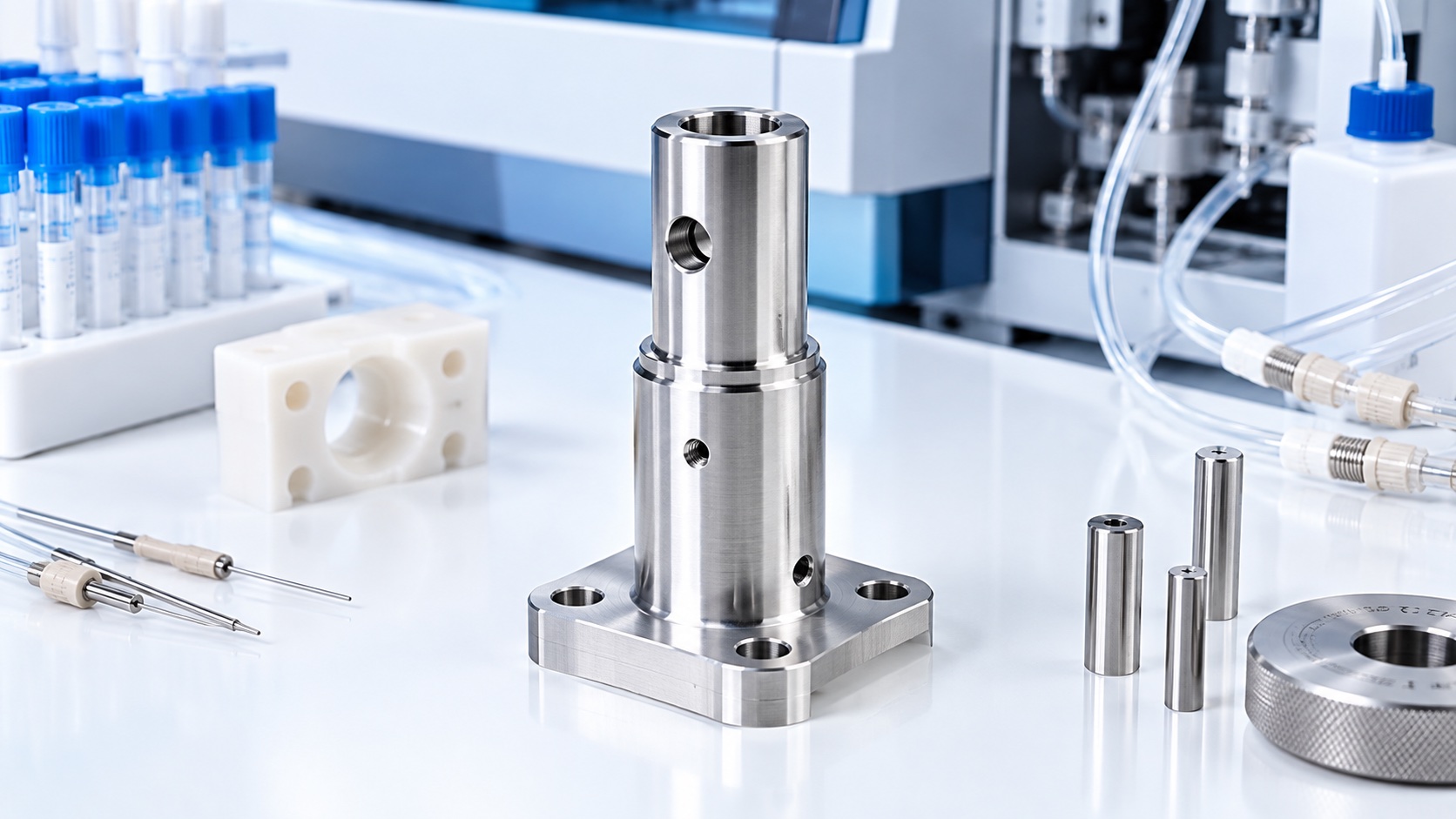
316L Hematology Analyzer Sample-Probe Alignment Holder: CNC Machining Case
Representative application
This case describes a representative 316L holder that aligns a sample probe in an automated hematology analyzer. The part combines a mounting face, two locating holes, a precision guide bore, split-clamp feature and protected shoulder for the probe assembly. It is a manufacturing example, not a claim for a certified analyzer. The instrument manufacturer remains responsible for sampling accuracy, fluid compatibility, carryover, cleaning efficacy and system validation. The machine shop controls material identity, released geometry, finish and agreed inspection evidence.

Released design inputs
The production package includes a controlled drawing, matching solid model, revision history and critical-characteristic list. It identifies the primary mounting face, guide axis, clamp slot, fastener thread, probe shoulder and passivated surfaces. The customer supplies the probe or master-gauge size, tightening torque, mating-frame definition and inspection state. Before quoting, the supplier reviews bore length, slot width, thin-wall stiffness, thread engagement, tool access and whether the final guide diameter is specified before or after clamp loading.
Material and blank control
Certified 316L stock is received with heat or lot documentation and sufficient allowance to establish stable references. Identity stays with the traveler through machining, passivation and packaging. The blank is checked for visible defects before setup. Material condition and stock form are not changed without approval because residual stress, surface response and dimensional movement can differ. Any passivation specification and certificate requirement are confirmed before the first article.
Machining sequence
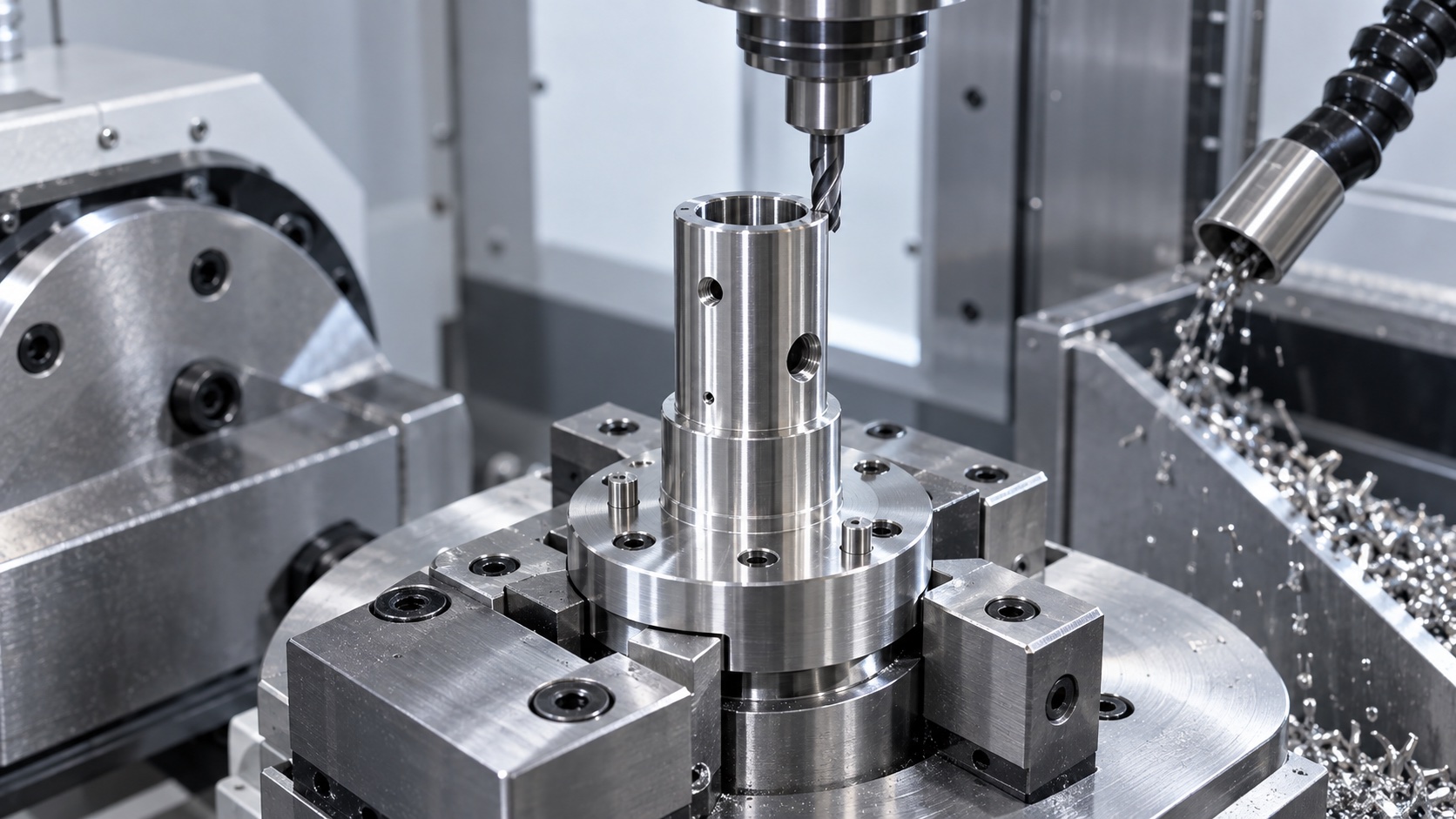
The first operation establishes the mounting face and accessible exterior datums. The guide bore and locating holes are rough-machined while the clamp section retains support. A controlled setup finishes the bore axis relative to the mounting face, then creates the split and fastening features according to the released process. Sharp tooling, managed heat and effective chip evacuation reduce work hardening and internal burrs. Edge finishing protects the probe and operator without rounding the locating shoulder or changing the clamp split.
Clamp-state control
A split holder changes shape as the fastener is tightened, so the inspection plan defines free-state and assembled-state requirements. A customer-approved master pin or probe gauge can be used with the specified torque fixture to check clamping and release. The machine shop records the screw type, torque method and gauge condition used for any functional check. This mechanical test confirms fit only; it does not demonstrate aspiration performance or the analyzer's motion accuracy.
Geometric inspection
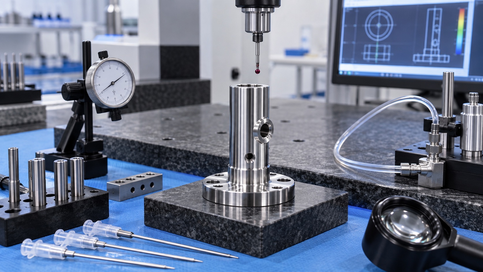
The first-article report covers mounting-face flatness, locating-hole position, guide-bore diameter and axis, perpendicularity, shoulder height, clamp-slot width, thread quality and edge condition. CMM inspection relates the bore to the mounting pattern, while bore gauges and optical tools confirm local features. Measurement temperature, fixture and drawing revision are recorded. Parts with scratches, embedded chips or damaged sealing and guide surfaces are segregated for documented disposition.
Passivation and cleanliness
After dimensional acceptance, the holder follows the specified cleaning and passivation route. Residues are removed from the guide bore, slot and threads, and critical dimensions are rechecked where treatment could reveal or alter defects. Handling tools and trays should not transfer ferrous contamination back to the part. Final visual inspection verifies dryness, surface condition and absence of loose particles. The process provides a clean machined component, not a sterile medical device.
Packaging and documentation
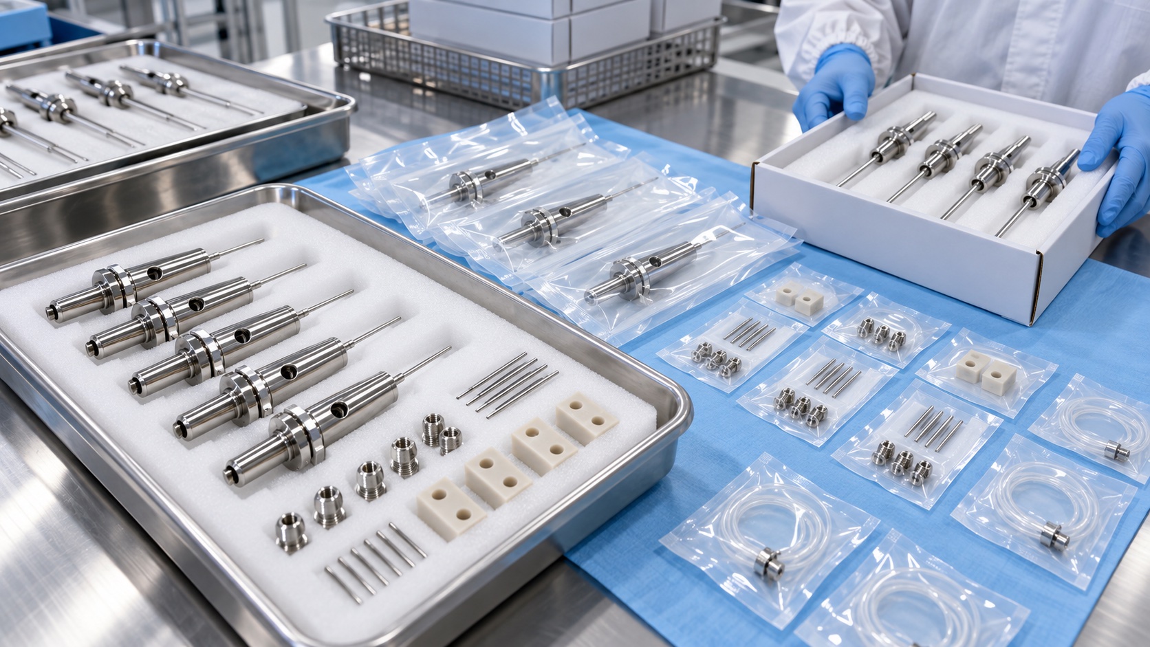
Each holder is separated to protect the guide bore, mounting face and passivated surface from contact damage. Labels identify part number, revision, material lot, finish lot, quantity and inspection status. Depending on the order, delivery records can include material certificates, first-article reports, passivation certificates, dimensional results, approved deviations and packing-list traceability. Protective plugs are used only if their material and cleanliness are approved for the receiving process.
Repeat production
For repeat orders, the CNC program, fixture revision, inspection routine and passivation specification remain under change control. Trend data for guide diameter, axis position and clamp response can reveal drift before assembly is affected. Forecast and batch size help plan traceable material and finishing capacity. Changes to the probe, mating frame, screw, torque, cleaning chemistry or wash geometry require a documented customer review because they can alter the validated system interface.
FAQ
Is this holder a finished diagnostic device?
No. It is a representative machined component. The analyzer manufacturer validates the complete instrument and assay workflow.
Why use a split-clamp design?
It can retain and release a probe with controlled force, but bore geometry, slot stiffness, screw and torque must be defined together.
How is the guide axis inspected?
CMM measurement relates the bore axis to the mounting face and locating pattern; bore gauges or master pins confirm local size and fit.
Why inspect after passivation?
Finishing can reveal residue or surface defects, and critical fits and threads must remain within the released requirements.
Does the holder prevent carryover?
No. Its geometry supports alignment and cleaning access; carryover must be validated on the complete analyzer fluid and wash system.
What documents can accompany delivery?
Material and passivation certificates, lot traceability, first-article and dimensional reports, and approved deviation records can be supplied.