
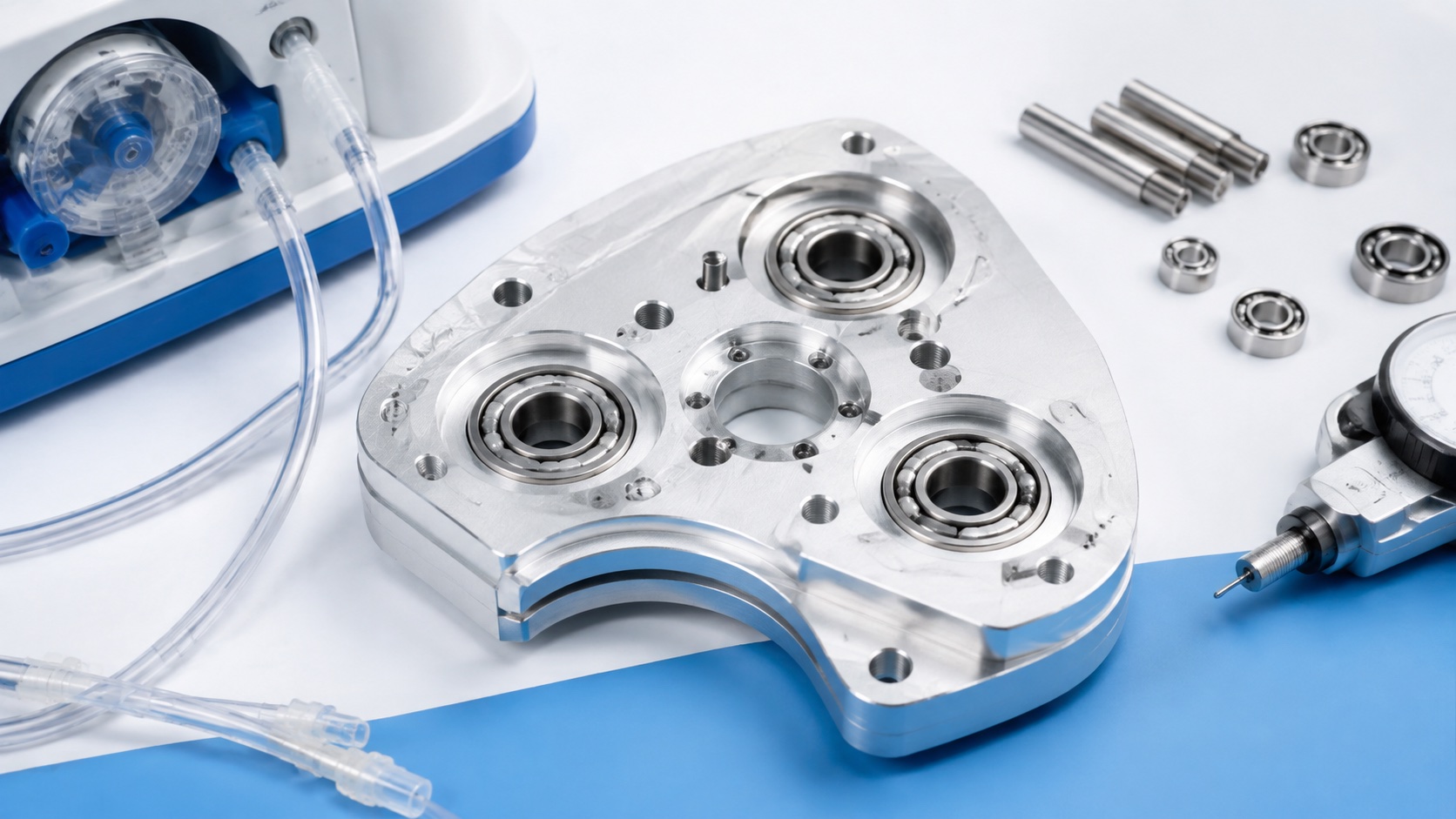
6061-T6 Five-Roller Infusion Pump Carrier: Precision CNC Machining Case
Representative application
This case describes a representative 6061-T6 carrier that supports five rollers in a peristaltic infusion pump drive module. It contains a central drive interface, repeated bearing bores, weight-relief pockets, mounting holes and a clocking feature. The example concerns component manufacturing, not a certified pump claim. The medical device manufacturer remains responsible for flow performance, occlusion settings, tubing compatibility, alarms, electrical safety and final validation. The machine shop controls the released geometry, material, finish and agreed records.

Released input package
The handoff includes a controlled 2D drawing, matching model and revision history. The drawing identifies the mounting face, drive axis, roller-station pattern, bearing fits, clocking feature, finish and protected contact zones. The customer provides the approved bearing and shaft specifications, assembly sequence and any mating gauges. Before quoting, the supplier reviews minimum web thickness, tool access, bore tolerances, coating allowance and whether the carrier will be inspected before or after bearing installation.
Material and blank planning
Certified 6061-T6 stock is cut with enough allowance for stable finishing. Lot identity stays with the traveler. The blank is reviewed for flatness and visible damage before the first setup. Roughing is distributed around the carrier so one side is not heavily relieved while the opposite side remains constrained. If a different temper or stock form is proposed, the customer must approve it because stiffness, residual stress and anodizing response may change.
Machining strategy
The first operation establishes the mounting face, drive bore and external references. Repeated pockets are rough-machined with a symmetric sequence, leaving material at the bearing stations. In a supported finishing setup, the drive interface and roller bores are completed from the common datum system. Tool paths use consistent entry and exit around each station to limit station-to-station variation. Final contouring and controlled deburring protect thin webs and prevent a sharp edge from contacting tubing or assembly personnel.
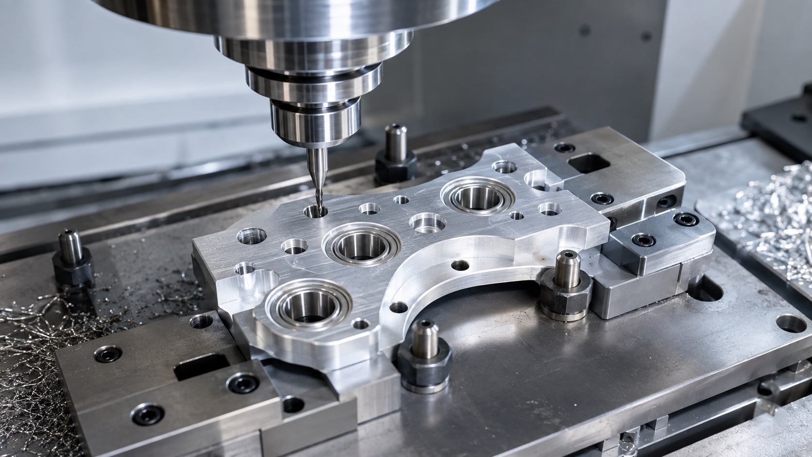
Bearing-bore and shaft alignment
Each bearing bore is checked for diameter, position and perpendicularity relative to the mounting face. The pattern is evaluated as a group, not only as five independent holes. If bearings are pressed into the carrier, installation force and support method are controlled so the thin frame is not bent. The device owner specifies the fit and bearing internal-clearance considerations. After installation, selected dimensions or roller runout are rechecked to identify distortion introduced by assembly.
Anodizing and masked zones
Anodizing provides surface protection and appearance, but uncontrolled buildup can close a miniature bearing fit or alter the drive interface. The drawing identifies masked bores, grounding areas and contact faces, and states which dimensions apply after finish. Finished parts are examined for burns, rack marks, color variation in cosmetic zones and coating damage at critical edges. Any rework near a bearing seat requires documented approval because it can change both fit and surface protection.
Inspection plan
The first-article report includes material identity, mounting-face flatness, drive-bore size and position, five-station true position, bore perpendicularity, carrier thickness, mounting-hole location and edge condition. Inspection records identify the CMM program, fixture and drawing revision. A customer-approved master or functional fixture can supplement the report. Component acceptance does not demonstrate delivered fluid flow; that verification occurs in the completed pump with the specified tube set and control system.
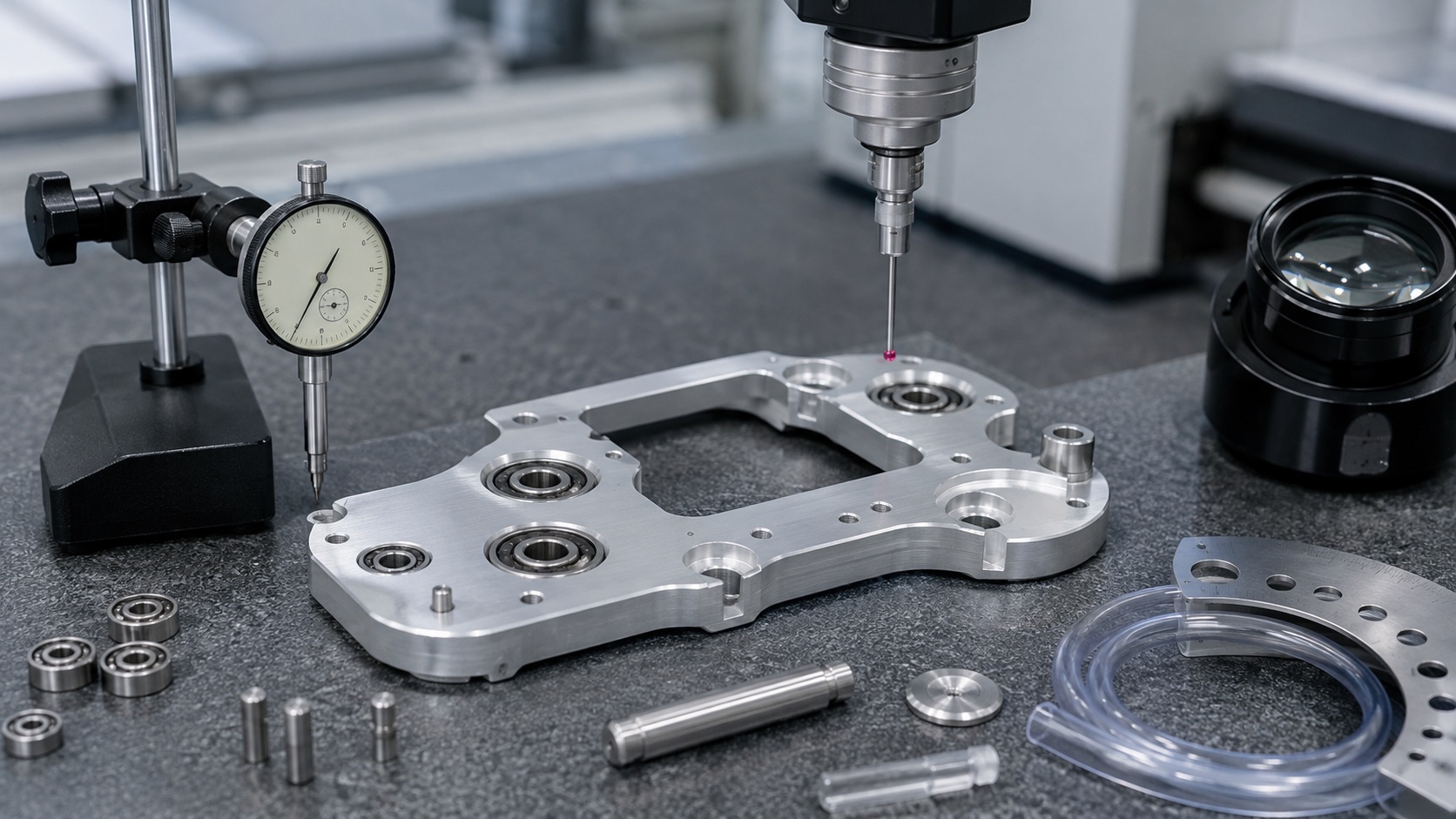
Cleaning and delivery
After finish and inspection, the carrier is cleaned to remove chips, abrasive particles and loose coating residue. Bearing bores, pockets and threaded holes receive particular attention. Parts are separated in trays or sleeves so precision faces cannot rub. Labels identify part number, revision, material lot, finish lot, quantity and inspection status. Packaging is described as clean and protective, not sterile unless a separate validated process is part of the purchase order.
Repeat-order control
For repeat production, the approved CNC program, fixture revision, inspection method and finish specification remain under change control. Trend data for the drive bore and roller pattern can reveal tool or fixture drift before it becomes a fit problem. Forecast and batch size support material and finishing capacity planning. Changes to bearing type, shaft size, tubing, platen geometry, finish or assembly force require a documented customer review because they can affect the validated mechanism.
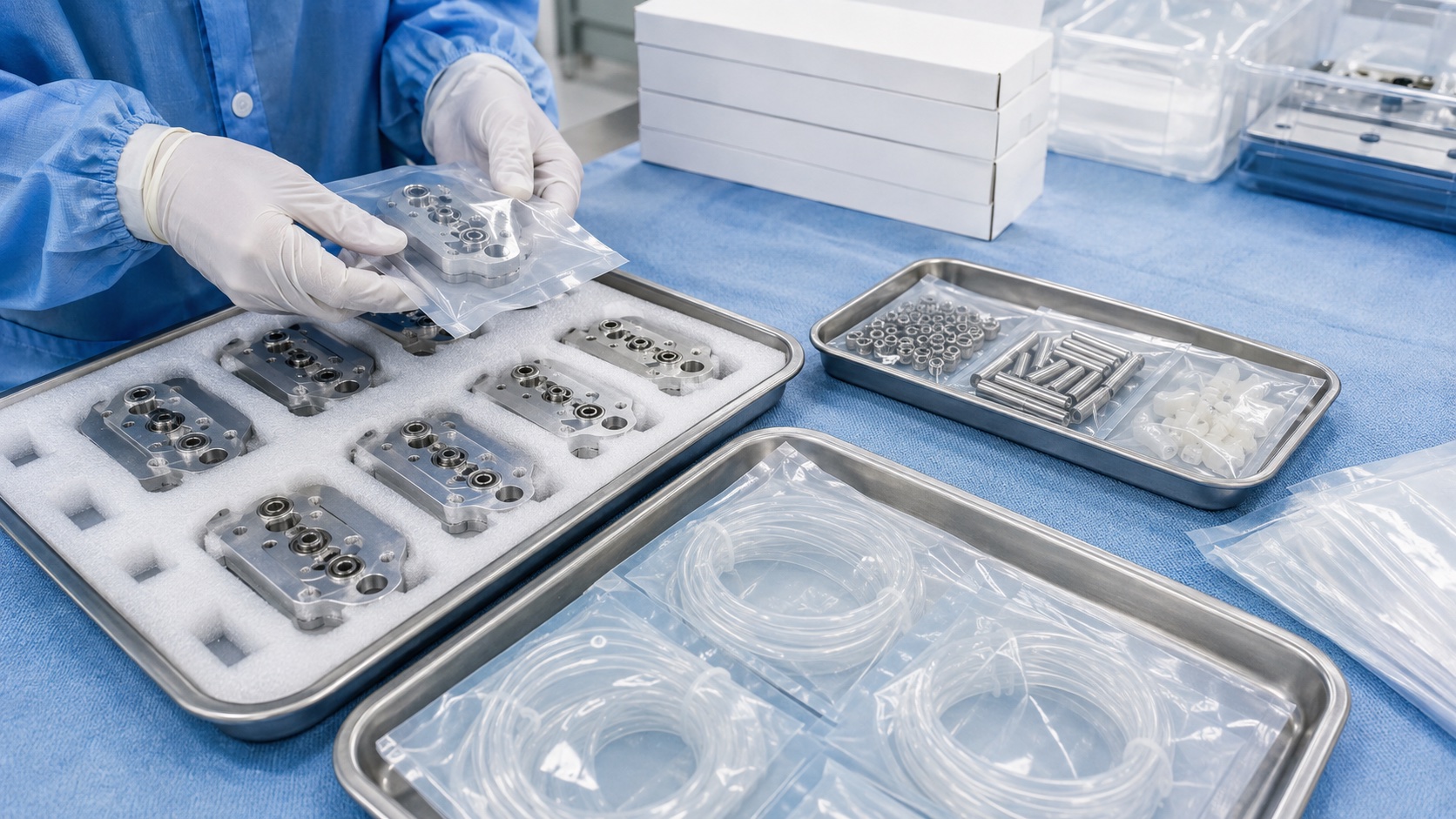
FAQ
Is this carrier a finished infusion pump?
No. It is a representative machined component. The device manufacturer validates and certifies the complete pump.
Why use 6061-T6?
It can offer low mass, machinability and common finishing options, subject to the device design's stiffness, cleaning and durability requirements.
How are five roller bores kept aligned?
They are machined and inspected from a common datum system, with position and perpendicularity evaluated across the complete pattern.
Why recheck after bearing installation?
Pressing bearings can distort a thin carrier or alter runout, so selected critical features should be confirmed afterward.
Can bearing bores be anodized?
Only as the released design allows. Tight fits are commonly masked or compensated and then verified after finishing.
What documents can accompany delivery?
Material and finish certificates, lot traceability, first-article reports, inspection results and approved deviation records can be supplied.