

7075-T6 Medical Centrifuge Sample-Carrier Hub Adapter: CNC Machining Case
Representative component
This case describes a representative 7075-T6 aluminum hub adapter that connects a centrifuge spindle interface to repeated sample-carrier mounting locations. The part includes a central pilot bore, mounting face, bolt circle, symmetric pockets and identification zone. It is a machining example, not a statement that a particular rotor has been certified. The equipment manufacturer controls stress limits, operating speed, fatigue life, dynamic balancing and containment. The supplier's responsibility is the released geometry, material identity, finish condition and agreed inspection evidence.

Drawing and handoff
The released package contains a matching drawing and solid model, revision history and a list of critical characteristics. The primary datum is the spindle-contact face, the central bore establishes the rotation axis and a clocking feature orients the repeated pattern. The customer supplies the mating gauge dimensions, fastener specification, post-finish tolerances and balance responsibility. Before quoting, the shop reviews wall thickness, pocket symmetry, thread engagement, inspection access and whether any balance correction features are allowed.
Material control
7075-T6 stock is purchased to the specified form and certificate requirement. Each blank is identified to its lot and inspected for damage before machining. The process leaves enough stock to finish the mounting face and pilot after rough material removal. If plate orientation or grain direction is controlled by the design, that information remains on the traveler. No alloy or temper substitution is made without written approval because mechanical strength, corrosion behavior and dimensional movement can change.
Roughing and stress management
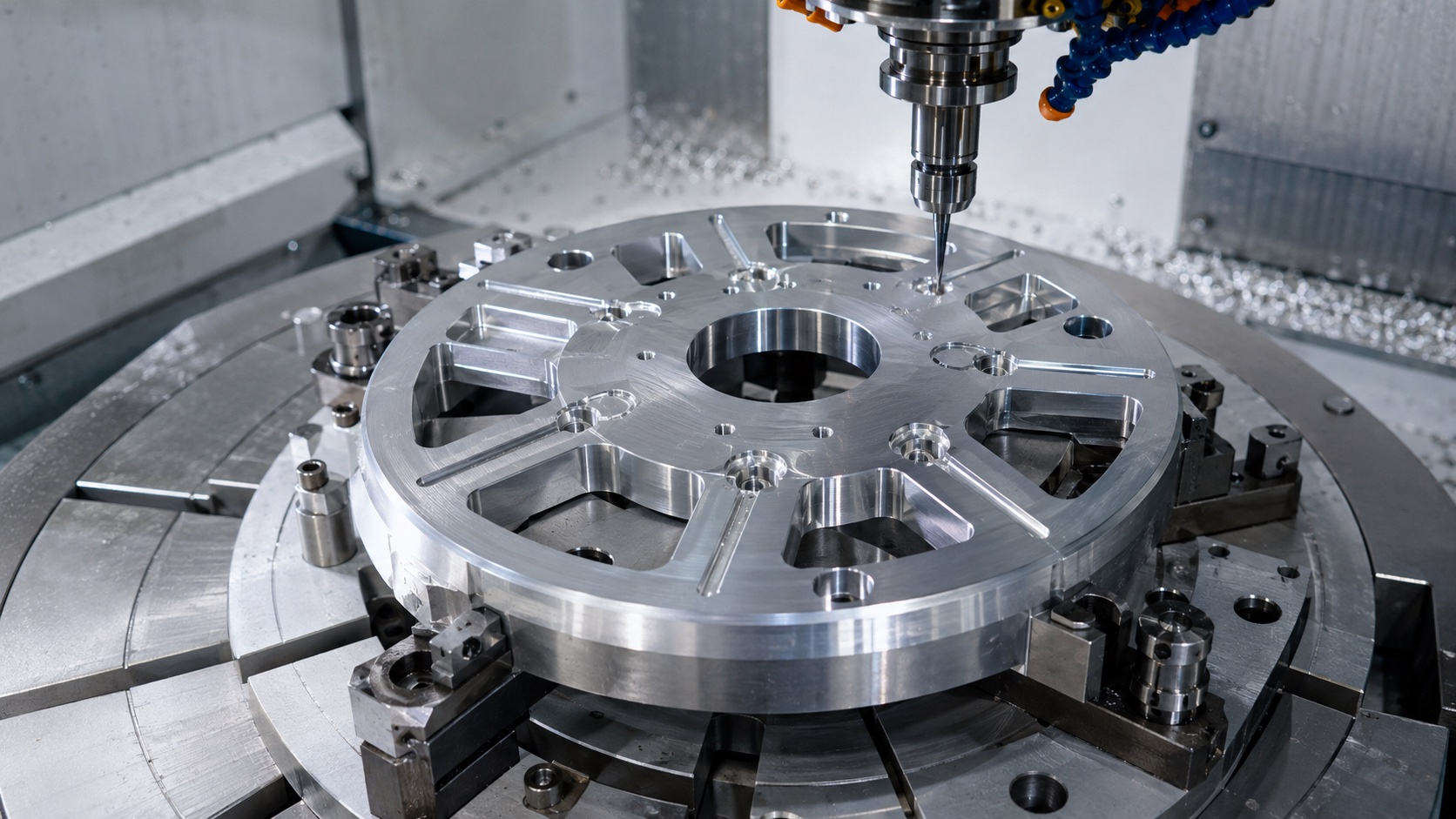
The adapter is rough-machined with material removed from both sides in a planned sequence. Symmetric roughing reduces the chance that the part becomes dished. A stabilization interval may be used before finishing the rotating interfaces. Fixtures support the broad face without concentrating clamp force near thin pockets. The program applies the same strategy to repeated features so geometry and removed mass remain consistent. Program revision, fixture identification and tool changes are recorded for first-article traceability.
Finishing the rotation axis
The mounting face and central pilot are finished from a controlled setup wherever practical. Cutter condition, bore size and temperature are monitored because a small axis error can appear as runout at the outer carrier locations. The bolt circle and clocking feature are related to the same datum structure. Threads are gauged, and entrances receive a consistent edge break so fasteners seat without loose burrs. Identification marking is placed only in the approved zone and at controlled depth.
Repeated carrier interfaces
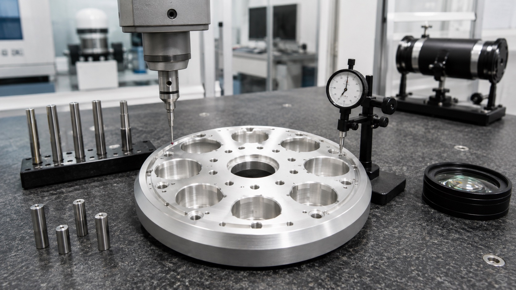
Each carrier location must match the drawing while remaining consistent with the other locations. Pocket depth, support height, hole position and edge condition are sampled around the adapter rather than measured at one convenient position. Tool wear can create a gradual difference between the first and last pocket, so the inspection sequence tracks position. Any removable bushings or inserts use approved material and installation force, followed by a check that installation did not distort the surrounding aluminum.
Inspection and balance handoff
The first-article report covers material, face flatness, pilot size and roundness, pilot-to-face relationship, bolt-circle position, pocket depth, thread quality and visual condition. Runout is measured on the defined fixture. Part mass can be recorded, but dynamic balancing is performed only to the customer's documented assembly state, speed, correction planes and residual-unbalance limit. Balance records identify the adapter serial number and any approved correction so results remain traceable.
Finish and packaging
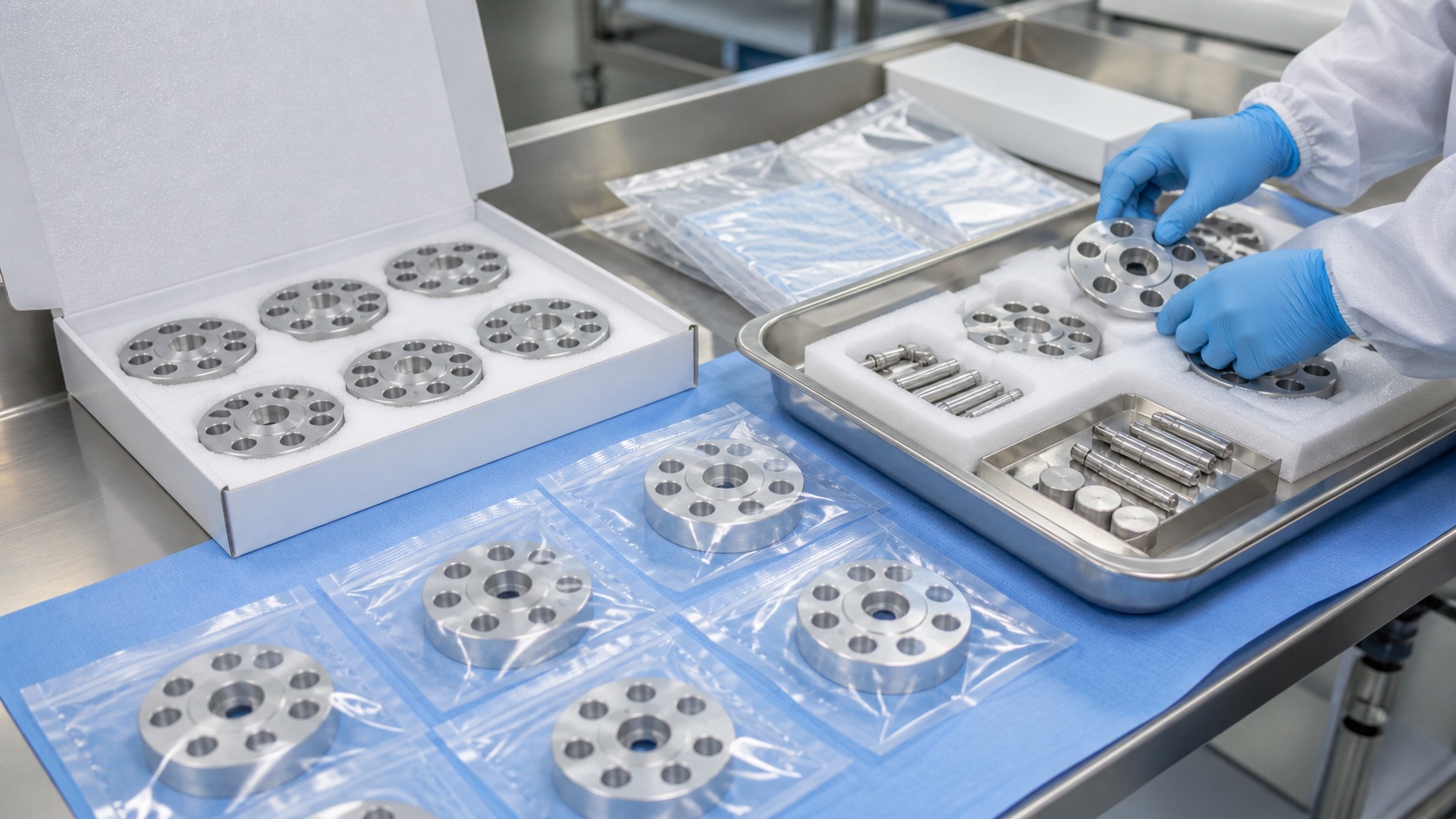
After dimensional acceptance, specified surfaces are anodized or otherwise finished with pilots, threads and contact zones masked as required. Critical features are rechecked after finishing. Parts are cleaned to remove chips, abrasive residue and loose coating. The mounting face and pilot are protected with separated trays or sleeves, and hard parts cannot strike each other in transit. Labels identify part number, revision, lot, serial number when required, quantity and inspection status. Packaging is protective and clean, not represented as sterile.
Repeat production
For repeat orders, the approved CNC program, fixture, inspection plan and representative sample remain under change control. Material lead time, forecast and batch size are reviewed so blanks from traceable lots can be planned. Trends in bore size, runout and repeated pocket position are monitored to identify tool or fixture drift. Changes to spindle fit, operating speed, carrier mass, finish or correction method trigger a customer review because they can affect the validated rotor system.
FAQ
Is this adapter a complete certified rotor?
No. It is a representative machined component. The centrifuge manufacturer validates the complete rotor and operating limits.
Why use 7075-T6?
It can provide high strength at low weight, but the final alloy and temper require design approval based on fatigue, corrosion and cleaning conditions.
How is runout inspected?
The mounting face and central pilot are checked on a defined mandrel or fixture, with the measurement method stated in the inspection plan.
Why measure every repeated location?
Tool wear or setup effects can create position-to-position differences, so sampling around the full pattern is more informative than one pocket.
Can the machine shop perform balancing?
Yes only when the customer defines assembly condition, test speed, correction planes, equipment and residual-unbalance acceptance.
What documents can ship with the part?
Material certificates, lot and revision traceability, first-article reports, finish records, runout data and agreed balance records can be supplied.