
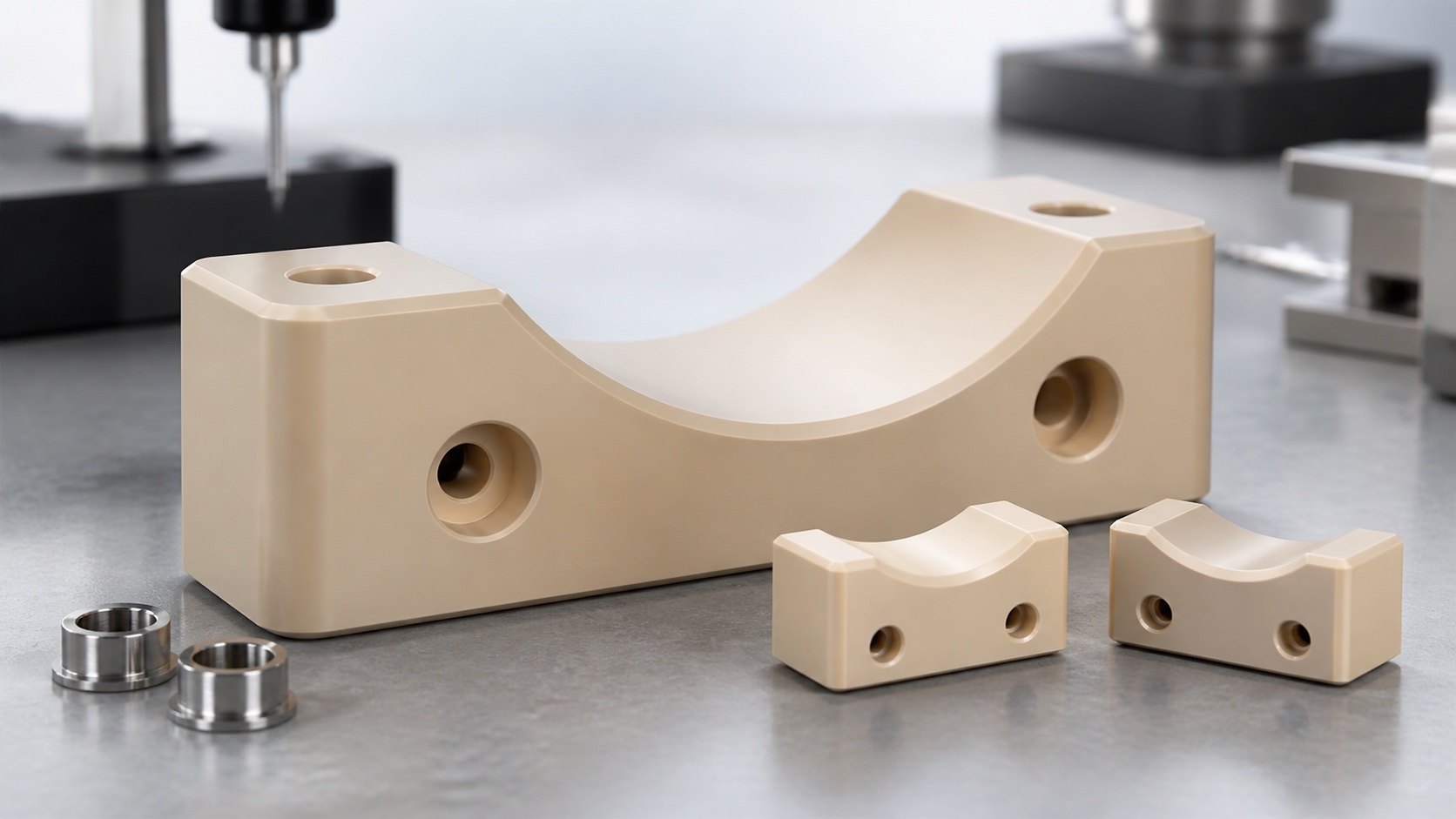
PEEK MRI Coil Locator Block: Precision CNC Machining Case
Representative application
This case describes a representative PEEK locator block used to position an accessory coil support within a medical imaging fixture. The component combines a broad mounting face, two precision pin bores, a keyed slot and a curved support surface. It is a manufacturing example rather than a claim for a specific certified device. The equipment manufacturer remains responsible for MRI safety classification, image-quality validation, patient-contact assessment and final assembly labeling. The machining supplier controls the specified geometry, material identity and production evidence.

Released design inputs
The production package contains a controlled drawing, matching solid model and revision history. It identifies the primary mounting face, secondary stop, pin-bore pattern, coil-support profile, threaded insert locations and protected cosmetic areas. The customer also supplies the approved PEEK grade, mating pin size, expected clamp load, cleaning agents and inspection report format. Before quoting, the shop reviews minimum wall thickness, tool access, achievable corner radii and whether the specified tolerances remain measurable after insert installation.
Material and blank preparation
The selected unfilled PEEK stock is received with lot documentation and enough machining allowance to establish stable datums. The blank is inspected for obvious damage and its identity stays with the traveler. Because polymer dimensions respond to temperature and released stress, rough machining removes material symmetrically where practical. A conditioning pause before finishing lets the part stabilize. Substituting another PEEK grade or filled polymer is not allowed without customer approval because stiffness, tool wear, appearance and imaging behavior may change.
Fixture and machining strategy
A dedicated soft-jaw fixture supports the mounting face and broad side walls without crushing them. The first operation creates reliable reference surfaces and roughs the main profile. A second controlled setup finishes pin bores, keyed slot and the curved coil-support surface from the common datum system. Sharp cutters and limited heat input reduce smearing and feathered edges. Tool paths avoid abrupt exits at thin walls, and the final pass leaves the locating faces free of witness steps that could change assembly position.
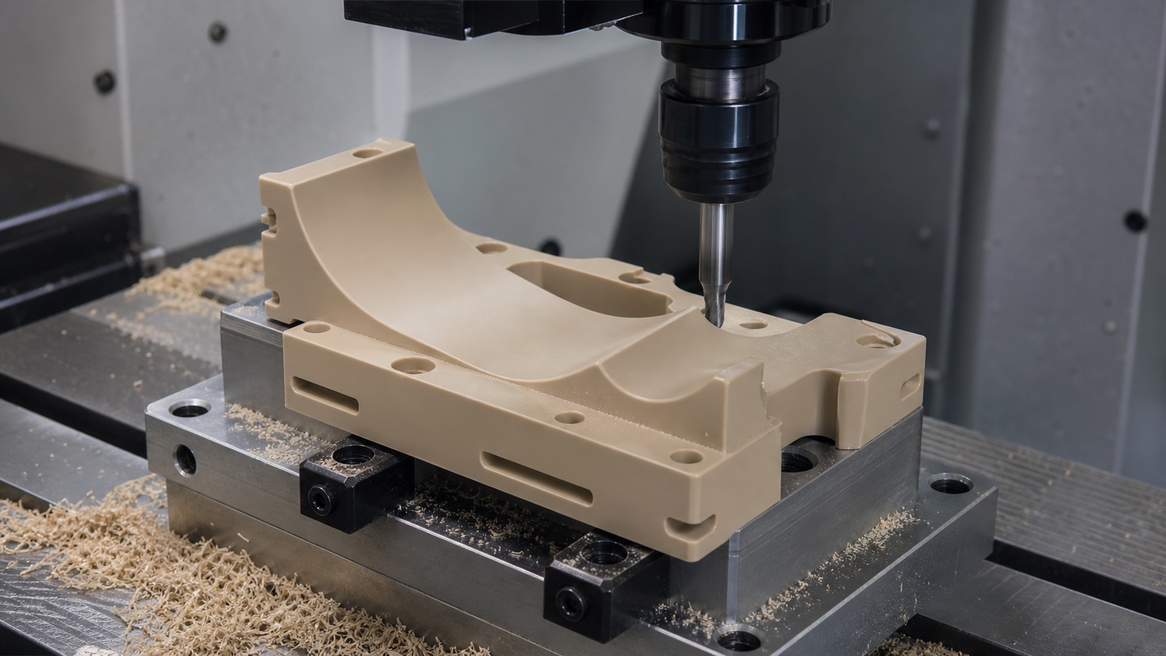
Bore, slot and edge control
The two pin bores control repeatable location, so their diameter, spacing and perpendicularity are inspected as a related pattern. The keyed slot prevents reversed assembly and needs a defined corner radius rather than an impossible sharp internal corner. Patient- or operator-accessible edges receive the drawing-specified radius, while datum edges are protected from over-deburring. Blind pockets are checked for retained chips. If threaded inserts are installed, the pilot feature and boss wall thickness are monitored before pressing or bonding.
Insert installation
Approved nonferromagnetic inserts are installed with the specified tool and depth stop. Installation force and orientation are controlled so the polymer boss is not split or distorted. Adhesive is used only when the released process permits it, with batch and cure information recorded. Critical dimensions around the inserts are rechecked afterward. The insert specification and completed assembly are still subject to the customer's MRI safety and compatibility assessment; component records support that process but do not replace it.
Inspection plan
The first-article report includes material identity, mounting-face flatness, stop perpendicularity, pin-bore size and position, slot width, curved-profile deviation, insert height and visual edge condition. CMM inspection establishes the relationship between features, while a customer-approved gauge can confirm mating fit. The report states measurement temperature and fixture method. Production sampling focuses on features affected by tool wear or polymer movement, and nonconforming parts remain segregated with a documented disposition.
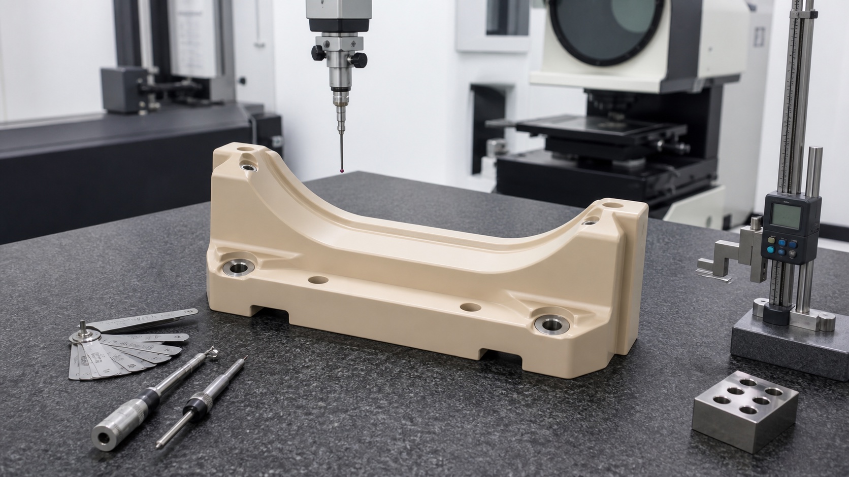
Cleaning, protection and delivery
After machining and inspection, the locator blocks are cleaned to remove chips, coolant traces and loose residue. Each part is separated so the profile, bores and inserts cannot abrade another component. Packaging is labeled with part number, revision, material lot, quantity and inspection status. The supplied packaging is clean and protective, not represented as sterile. Delivery documentation can include material certificates, first-article results, in-process inspection records, insert lot data and approved deviations.
Scaling from prototype to repeat orders
Prototype builds validate tool access, fixture support, fit and inspection methods before volume increases. For repeat orders, the approved program, fixture revision, gauge status and acceptance sample are kept under change control. Forecast and batch-size information help the supplier plan material and inspection capacity. Any change to PEEK grade, mating pins, insert type, cleaning chemistry or load condition triggers a documented review because those inputs can alter dimensional stability and service behavior.
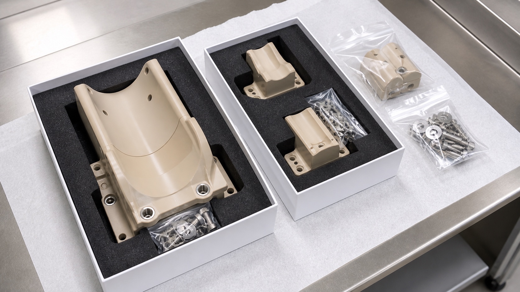
FAQ
Is this locator block an MR Safe finished device?
No. It is a representative machined component. The medical equipment manufacturer evaluates and labels the complete assembly for MRI use.
Why use unfilled PEEK?
It can offer strength, insulation and consistent machining, but the customer must approve the exact grade for mechanical, cleaning and imaging requirements.
How are the locating bores controlled?
Their diameter, spacing and perpendicularity are machined from common datums and verified together by CMM, gauges or both.
Why inspect after insert installation?
Insertion force can distort a polymer boss or change nearby dimensions, so critical features are confirmed after the assembly step.
Is the packaging sterile?
No. The case specifies clean protective packaging only unless a separately validated sterile supply process is included in the order.
What records can be delivered?
Material certificates, revision and lot traceability, first-article reports, inspection results, insert records and approved deviation documentation can be supplied.