
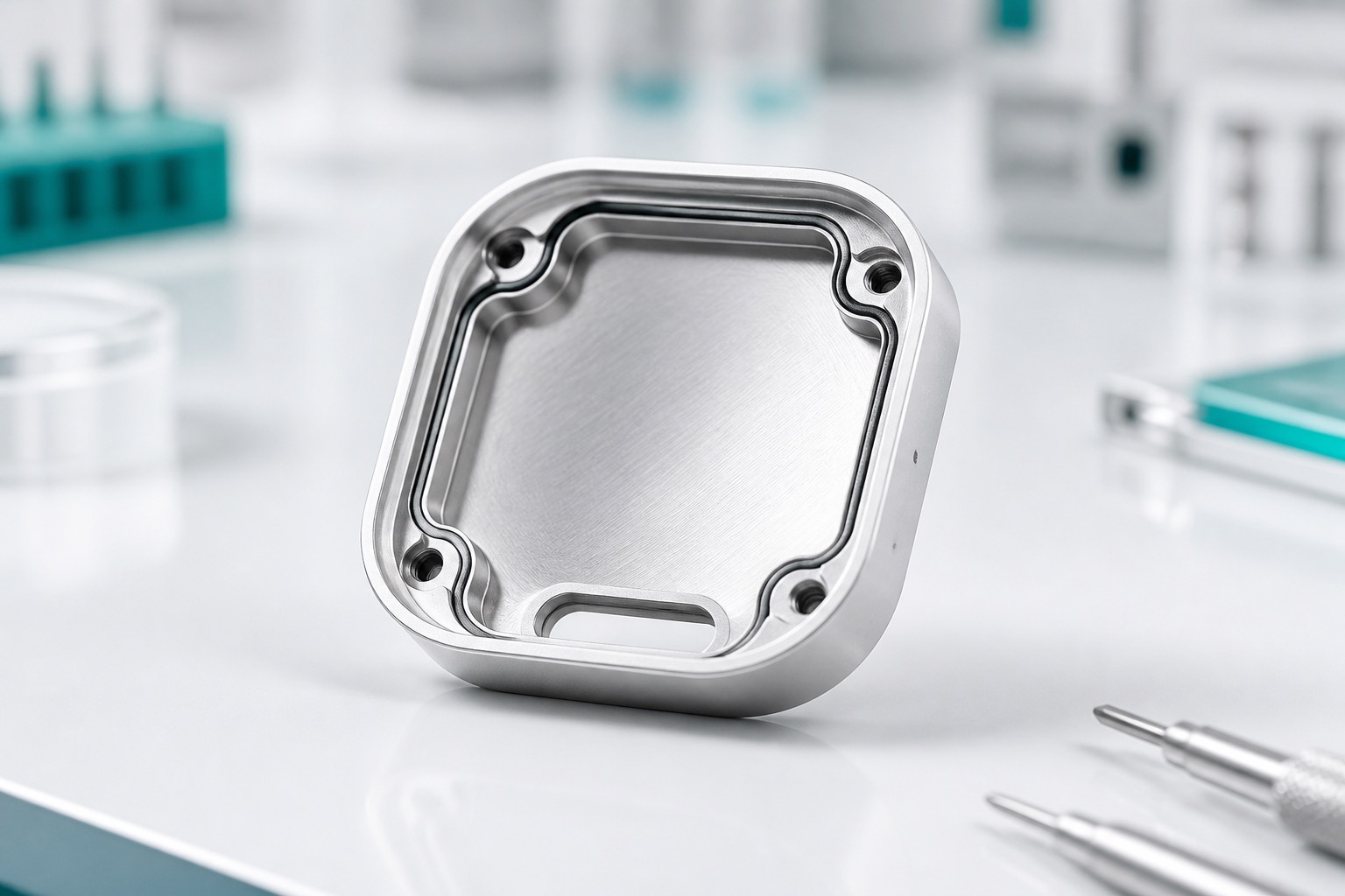
6061 Aluminum Wearable Patient Monitor Rear Cover: CNC Machining Case
Representative application
This case describes a representative 6061 aluminum rear cover for a wearable patient monitoring device. The part supports the electronics module, provides a continuous gasket groove and locates screw bosses, charging details and sensor reference surfaces. It is a machining case, not a certified device claim. The final customer remains responsible for biocompatibility, electrical safety, ingress protection and complete device validation. The machine shop's role is to produce the mechanical interface consistently and document the specified features.

Input package
A strong production handoff begins with a released drawing, solid model and revision history. The drawing identifies the outer cosmetic surface, inner board shelf, gasket groove, screw bosses, connector pocket and any surfaces that must remain free of coating. The customer provides gasket size, compression target, torque assumptions and finish requirements. Before quoting, the shop reviews wall thickness near the groove, cutter access in rounded corners, thread engagement and whether inspection can reach the specified datums.
Material and blank planning
6061 aluminum is often selected for light weight, machinability and good response to anodizing, subject to the device design review. The blank should leave enough stock for a stable finishing pass on the gasket land after roughing stress has been removed. Fixturing must support thin walls without leaving marks on visible or sealing surfaces. Lot identity should be kept with the traveler so material certificates, finish records and inspection data remain connected to the shipped covers.
Machining strategy
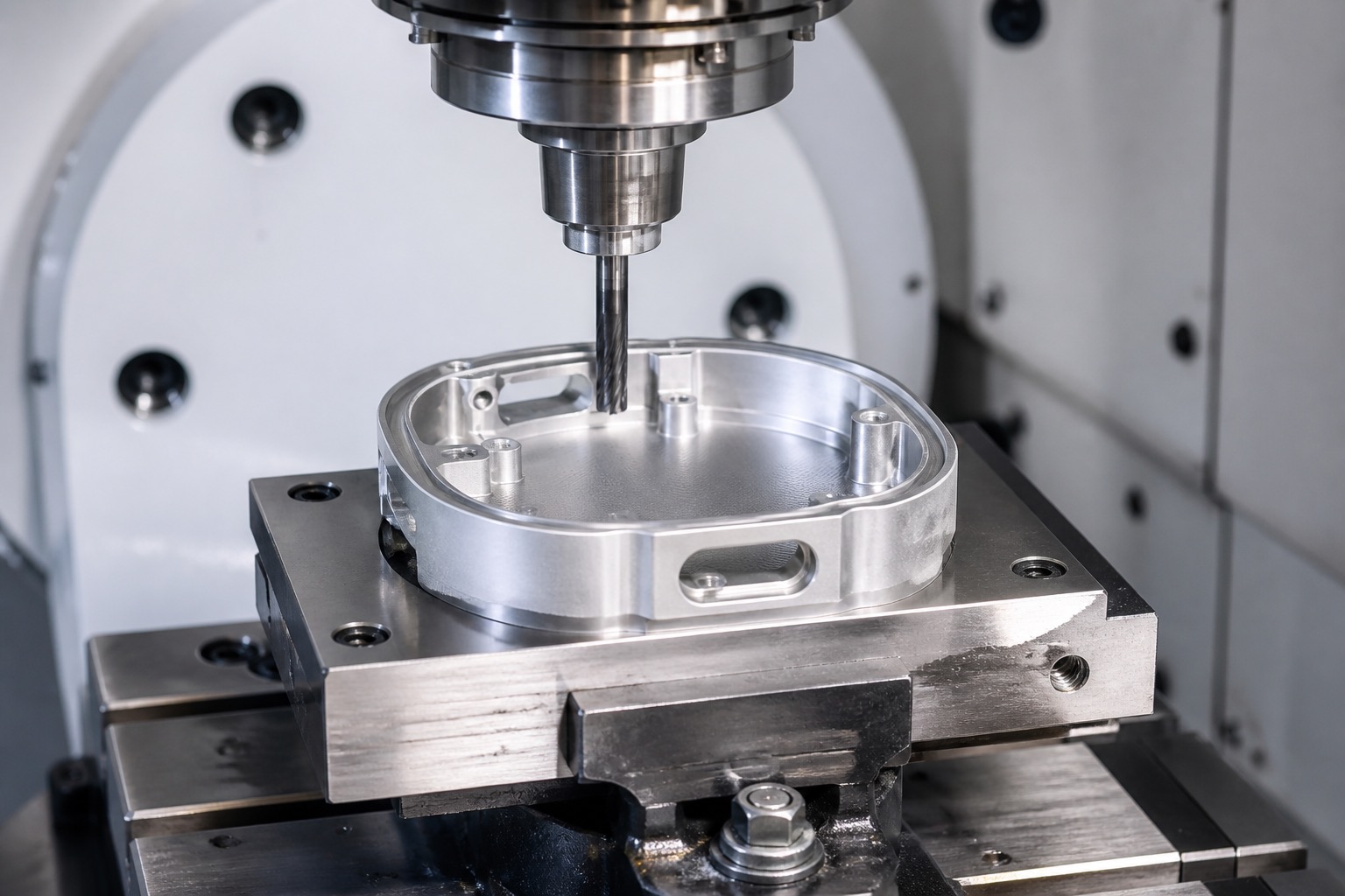
The process can establish the external reference face first, rough the pocket, then finish board shelves, screw bosses and the continuous gasket groove in controlled setups. A final contour and deburr step protects the hand-contact edges while preserving seal geometry. Small corner radii in the groove require suitable cutter diameter and tool wear control. Connector and charging features should be machined relative to the board-mount datums, not treated as isolated cosmetic openings.
Gasket groove control
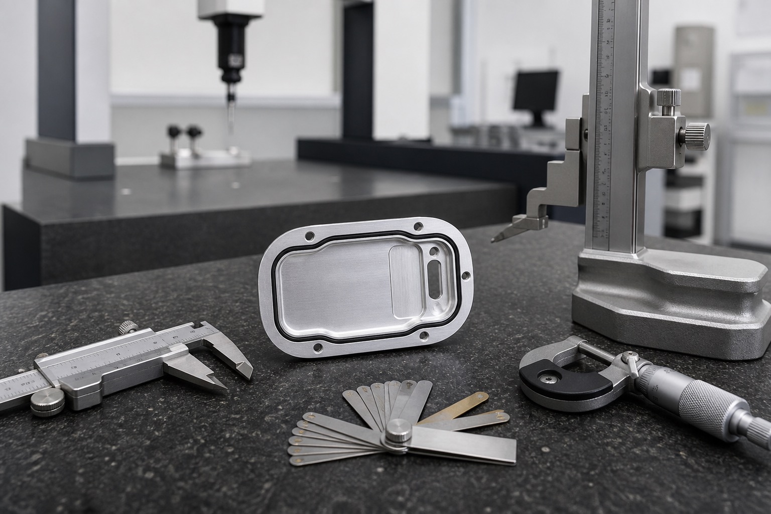
The groove is the main risk area. Depth, width, corner radius and surface condition affect gasket compression. A raised burr, coating build-up or local thin-wall distortion can create a leak path even when the cover looks clean. The drawing should state whether dimensions are before or after anodizing and which finish zones are masked. Sample parts can be inspected with optical measurement, depth gauges and flatness checks across the sealing land.
Surface finish and appearance
Medical equipment housings often need a controlled appearance as well as a functional surface. Tool marks, clamp marks and handling scratches should be separated into cosmetic and functional acceptance zones. Anodizing can improve appearance and wear resistance, but it changes color consistency and may affect tight holes or threads. The part should be protected immediately after finishing so the gasket land and sensor references are not damaged by parts rubbing together.
Inspection and records
A first-article report can include material verification, key dimensions, groove profile, boss height, hole position, thread quality, finish notes and images of important features. Production checks should monitor tool wear around the groove and window areas. Records need to identify revision, lot, fixture state and measurement method. If the customer requires leak or ingress testing, the test must be defined by the device owner and performed on the specified assembly state.
Packaging and delivery
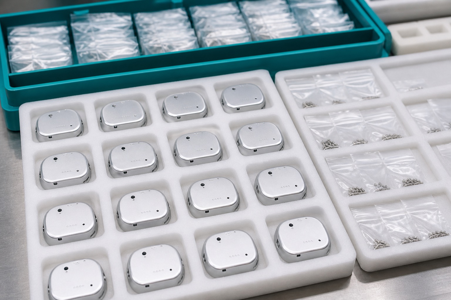
Clean the rear covers after machining and finishing to remove chips and loose residues. Use trays, sleeves or individual wrapping that keep the visible surface, groove and sensor references separated. Labels should show part number, revision, lot and quantity. The delivery package can include inspection reports, material documents, finish certificates and approved deviations. For repeat orders, storing fixture and inspection knowledge reduces risk when demand moves from prototype to pilot production.
FAQ
Is this rear cover a finished medical device?
No. It is a machined component case. Device certification and validation are controlled by the medical device manufacturer.
Why choose 6061 aluminum?
It offers light weight, machinability and common finishing options, but the final choice depends on the device design, cleaning process and use environment.
What makes the gasket groove difficult?
Continuous grooves combine depth, width, corner radius, burr control and wall stiffness; small errors can change gasket compression.
Should dimensions be checked before or after anodizing?
The drawing should define this. Critical close fits, threads and seal features often need post-finish confirmation or masking rules.
What documents can be supplied?
Material certificates, dimensional reports, finish records, lot traceability, photos of critical features and approved deviation records can be included.
Can the supplier perform ingress testing?
Only if the customer defines the assembled condition, gasket, fasteners, torque, method and acceptance limit. Component machining alone is not enough.