
Ti-6Al-4V Dental Surgical Guide Sleeve: Precision Turning Case
Representative product brief
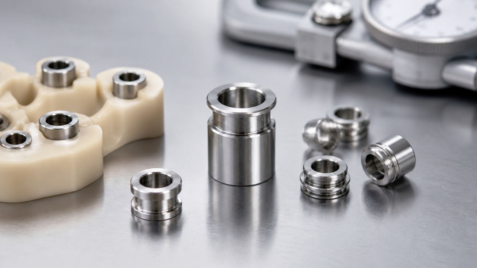
This case describes a representative Ti-6Al-4V sleeve intended for a dental surgical guide assembly. It is a manufacturing example, not a record of a specific patient device, customer order or clinical validation. The part combines a precision bore, retention outside diameter, seating shoulder and flange. These features guide a mating instrument and locate the sleeve in a guide body designed by the device manufacturer. The owner defines the guide plan, instrument clearance, retention method, cleaning and final validation. The machining supplier produces the released geometry, performs the agreed checks and preserves material and revision traceability.

Design inputs before quotation
The RFQ should include a released drawing, matching model and an assembly section through the guide body. It identifies the bore axis, outside fit diameter, flange face, insertion direction and any anti-rotation feature. Confirm the mating drill or key, guide-body material and hole-manufacturing process. Ask whether the sleeve is pressed, bonded or replaceable and whether a representative coupon will be available for first-article fit testing. The drawing must distinguish dimensional tolerance from functional clearance. If the guide body changes from one polymer or printing process to another, the fit needs a new review rather than an automatic reuse of the old sleeve.
Titanium stock and turning plan
The representative material is Ti-6Al-4V in the grade and supply condition specified by the device owner. Bar certificate and lot identification remain with the order when required. The turning plan establishes a stable axis, drills and finishes the bore, then completes the outside diameter, shoulder and flange with as few datum transfers as practical. Roughing leaves finishing allowance, and chuck pressure is controlled to avoid distorting the thin wall. Coolant, chips and tool condition are managed to prevent bore scoring. A cutoff and second operation may be needed for the rear face; that setup locates from a finished feature and includes a runout check.

Edges and functional surfaces
A controlled entry chamfer can help the mating instrument enter without catching. The flange face and shoulder establish seating and should not be rounded indiscriminately. The rear bore edge needs complete burr removal without creating a bell-mouth. Inspect the bore for taper, chatter and transferred material. Surface-treatment requirements are specified by the design owner; any process that adds thickness or changes friction is included in the fit review. Cosmetic brightness is not an acceptance criterion unless the drawing defines it. Functional surfaces are protected through cleaning, inspection and handling.
First-article inspection
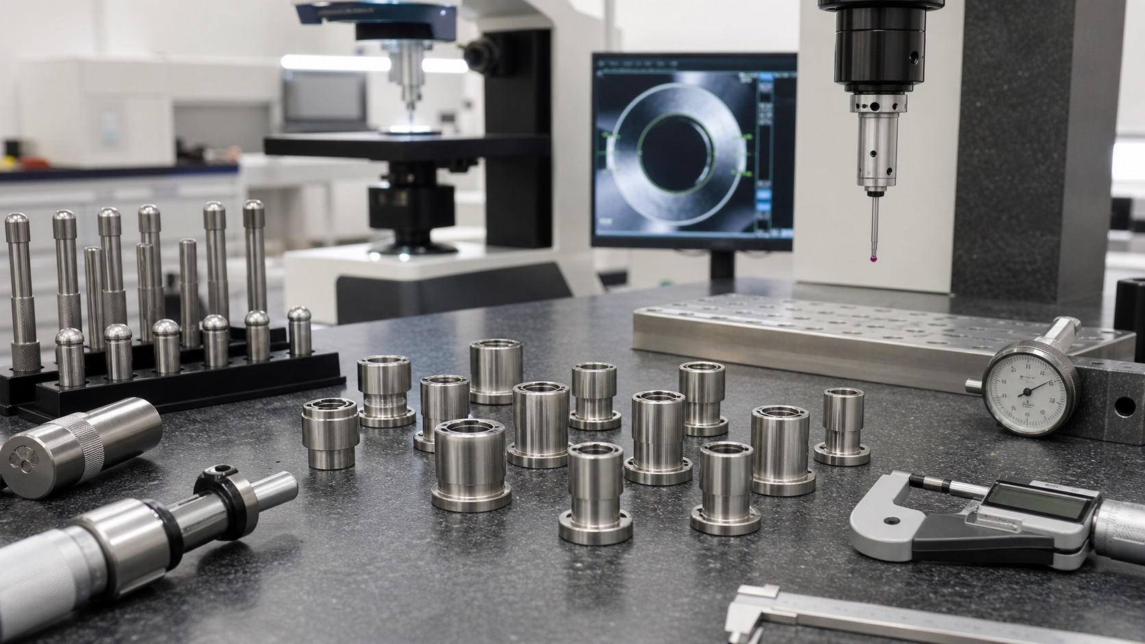
The first-article report can include material identity, bore and outside diameters, flange thickness, overall length, shoulder location, runout and edge condition. Use a measurement method capable of resolving the specified tolerance and record the gauge identification. A functional gauge or mating tool can confirm free movement, while a guide coupon can check retention and seating. Those tests use acceptance limits from the device owner. Photos of the bore ends and flange support visual review. If treatment occurs after machining, repeat the dimensions affected by the treatment before release.
Fit verification and lot control
Fit is a property of the sleeve and receiving guide feature together. Trial insertion should use the defined guide material, hole process and environmental condition. Record insertion or pull-out criteria only if the designer supplies a controlled method. During production, monitor bore and outside diameter trends rather than waiting for a final nonconformance. Segregate material lots and revisions, and do not mix sleeves made to different fit classes. Sampling frequency and any functional test belong in the control plan approved for the order.
Cleaning and packaging
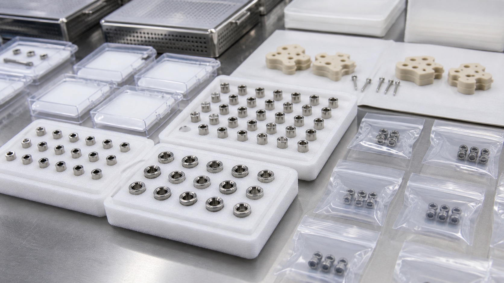
After burr removal and final inspection, clean the bore and flange according to the specified cleanliness level and check for residual chips. Small sleeves are separated in trays or compartments to prevent abrasion and loss. Labels identify part, revision, material lot and quantity. The packaging shown in images is illustrative and does not claim a sterile barrier. Delivery documents may include the material certificate, first-article or lot inspection report, treatment record and approved deviations. This lets the receiving team connect every package to the correct guide design.
Repeat production handoff
Once the first article is approved, retain the controlled program, setup sheet, tool-wear limits and gauge plan. For repeat orders, verify that guide-body material, hole process, mating instrument and fit requirement have not changed. State prototype, batch and annual quantities separately because inspection and setup effort affect price. If a new treatment or sterilization exposure is introduced, the device owner reviews fit and material behavior before release. A complete handoff reduces assumptions and supports consistent sleeves across lots.
FAQ
Is this a patient-specific implant?
No. This is a representative sleeve manufacturing case; the device manufacturer defines the intended use and validates the guide system.
Why use Ti-6Al-4V?
It can provide useful strength and corrosion resistance, but the device owner must approve the exact grade and application.
Which dimensions are most important?
Bore diameter, outside fit diameter, their axis relationship, flange thickness, shoulder location and edge condition are typical critical features.
Can a pin gauge replace all inspection?
No. It can confirm a functional limit, while quantitative bore, runout and flange measurements may still be required.
How is press fit verified?
Use the specified guide material and hole process with an approved insertion or retention method supplied by the design owner.
What documents can accompany delivery?
Material certificates, revision and lot traceability, first-article or lot reports, treatment records and approved deviations as ordered.