
CNC Machined 6061-T6 Portable Ultrasound Probe Connector Housing
This product case focuses on a CNC machined 6061-T6 connector housing used at the probe interface of a portable ultrasound device. The part protects the electrical connector, supports the cable exit, provides a repeatable sealing groove and gives the assembly a rigid datum for service and production testing.
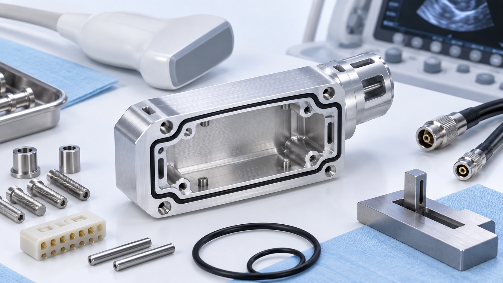
The starting requirement combined a rectangular connector pocket, four primary screw bosses, a circular cable strain relief end, a continuous O-ring groove and several thin wall sections. The customer needed a satin anodized surface, controlled connector alignment and clean delivery suitable for medical equipment assembly.
We used 6061-T6 aluminum billet because it gives the housing enough stiffness without making the probe cable assembly heavy. The machining process was planned in stages: rough milling of the outside envelope, semi-finishing of the pocket, controlled finishing of the connector cavity, then a final pass on the sealing face and screw boss pattern.
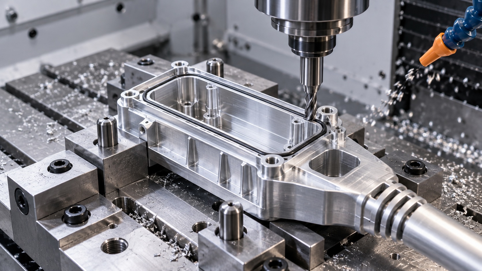
The main challenge was keeping the connector cavity flat and square while leaving enough wall thickness around the O-ring groove. A custom soft-jaw fixture supported the outside contour without marking the visible anodized surfaces. Finishing tools were selected with small corner radii to avoid sharp stress points and to produce a consistent sealing edge.
After machining, the housing was deburred under magnification. Particular attention was given to the O-ring groove, cable exit and screw counterbores because small burrs in these areas can cut seals or interfere with assembly torque. Threaded holes were checked before surface finishing and protected during anodizing review.
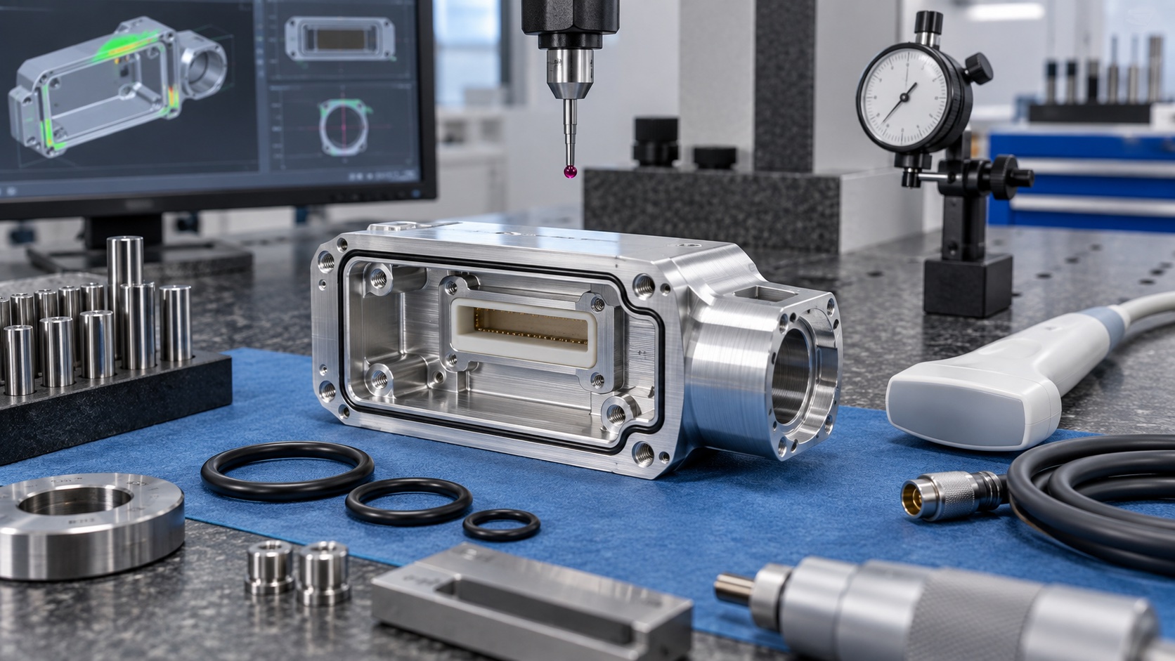
Inspection focused on functional relationships rather than only outside size. We checked connector cavity position, flatness of the mating face, O-ring groove depth, screw boss location, cable exit alignment and surface finish. Sample O-rings and an assembly connector were used for a practical fit check before the batch moved to packing.
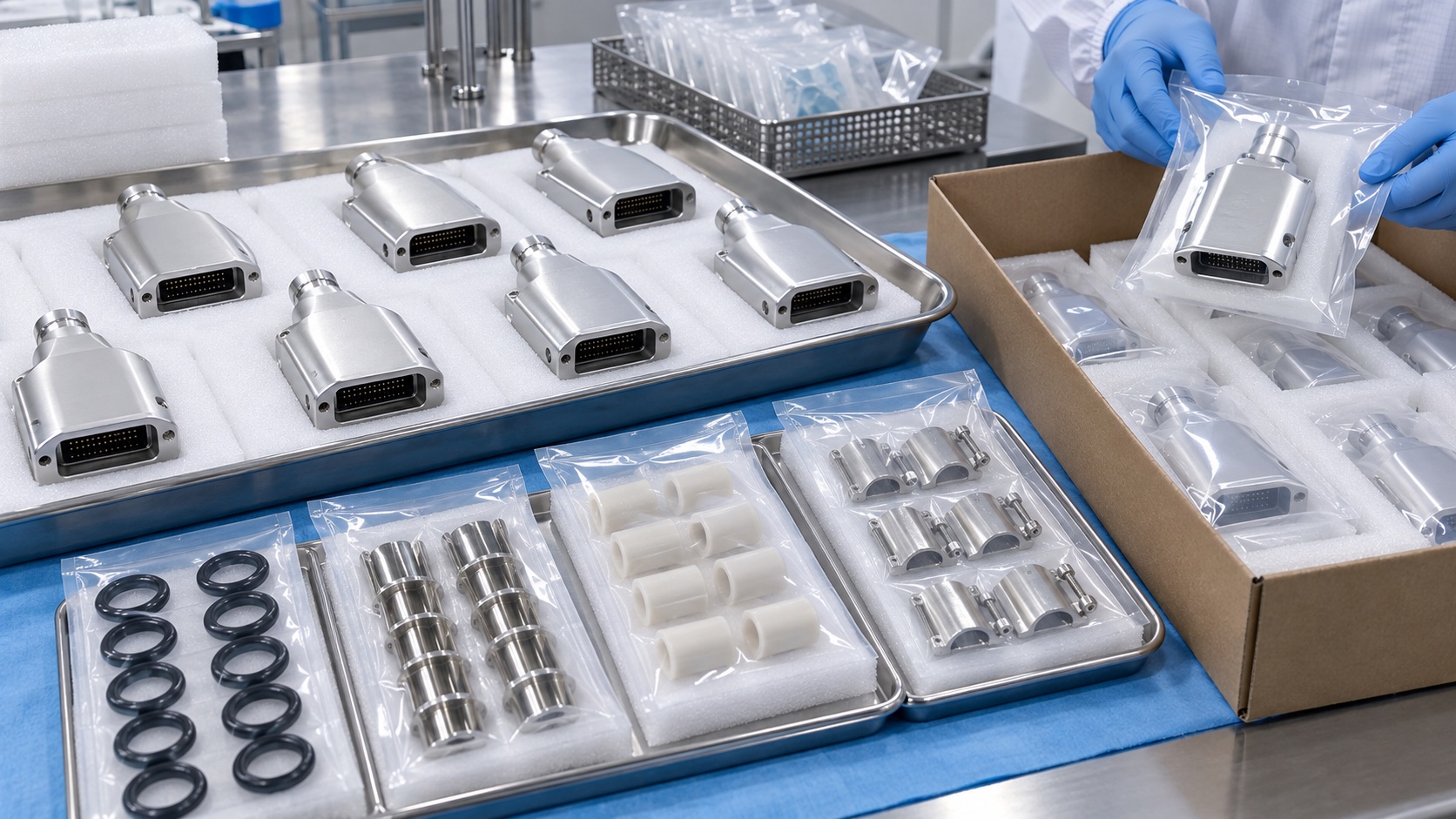
For delivery, each housing was packed with protective separation. PEEK insulating sleeves, stainless inserts and rubber O-rings were grouped by material to prevent scratches and contamination. The result was a ready-to-assemble housing set for a portable ultrasound device program.
FAQ
What material was used for the housing?
The housing was machined from 6061-T6 aluminum and prepared for a satin anodized finish.
Which features were treated as critical?
The connector cavity, mating face flatness, O-ring groove depth, screw boss position and cable strain relief pocket were critical.
Why use a soft-jaw fixture?
Soft jaws support the contour, reduce vibration and protect visible surfaces before anodizing.
How were burrs controlled?
The O-ring groove, cable exit and counterbores were deburred under magnification and then checked before packing.
Was a practical fit check performed?
Yes. Sample O-rings and a mating connector were used to confirm assembly feel and sealing interface consistency.
How was the batch packaged?
Housings, PEEK sleeves, stainless inserts and seals were separated in protective clean packaging for medical device assembly.
Contact: tanghangyun@oemach.com