
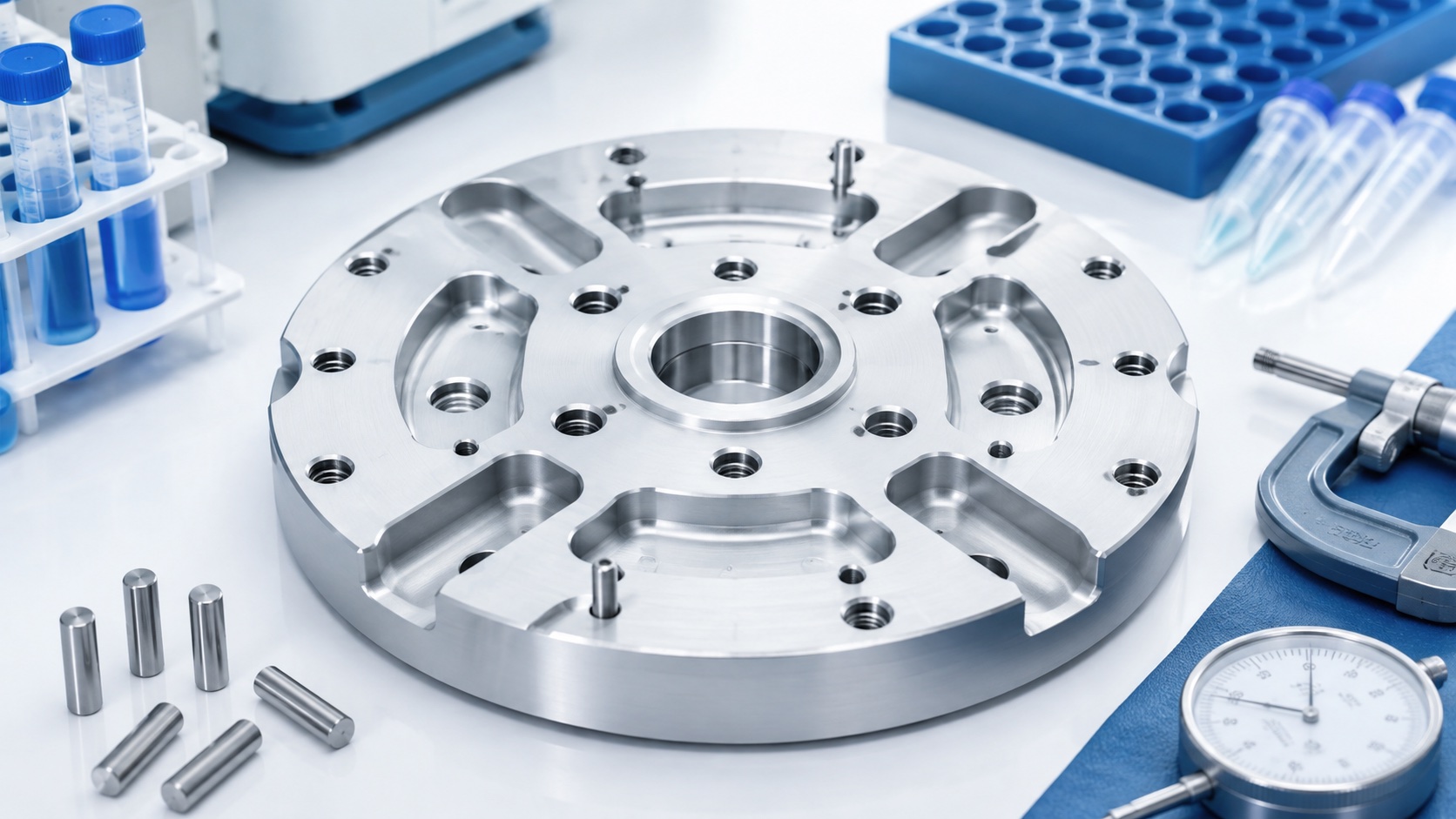
This product case describes a CNC machined 7075-T6 aluminum rotor adapter plate for a medical laboratory centrifuge. The part connects the drive interface to a replaceable rotor layout and must keep the sample pattern concentric during repeated high-speed operation. The customer required a rigid but lightweight component with stable flatness, accurate dowel positions, clean chamfers and packaging suitable for medical equipment assembly.

Application Background
Medical centrifuges are used in laboratories, diagnostic workflows and sample preparation systems. Although the adapter plate does not contact the sample directly, it influences rotational stability, tube position and service reliability. In this case, the plate included a large central bore, circular reference surfaces, radial weight relief pockets, counterbored mounting holes, dowel holes and small balancing details. The component had to match existing equipment interfaces while leaving room for future tube layout variations.
The selected material was 7075-T6 aluminum. This alloy helped reduce rotating mass while providing the strength needed around the mounting holes and center hub. Because the final part could receive anodizing, the machining plan also needed to keep cosmetic tool marks consistent and protect surfaces that would later serve as assembly datums.
Manufacturing Plan
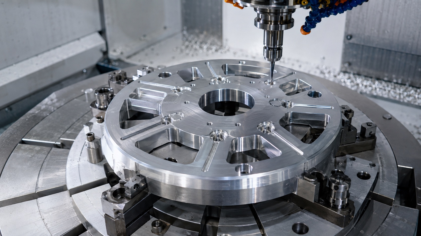
The process started with blank preparation and rough machining to remove excess material evenly around the plate. A dedicated fixture located the blank by the center area and supported the outside diameter to limit vibration. After roughing, the part was turned and milled through a semi-finish stage so that remaining stress could settle before the critical bores and hole patterns were finished. The final setup used the center datum, mounting face and radial orientation pins to keep the complete pattern aligned.
Pocket machining was programmed symmetrically to avoid unbalanced material removal. Counterbores were finished with controlled tool engagement to keep bottom surfaces flat. The central bore was completed after the major pocketing work, so the finished datum reflected the final part condition. Edges were deburred by hand under controlled magnification, with special attention to tube-adjacent radii, mounting holes and the lower face where burrs could affect seating.
Quality Control
Inspection covered the main functional dimensions and the rotating behavior of the plate. CMM measurement confirmed the position of counterbores and dowel holes relative to the center bore. Height checks verified pocket depth and step relationships. Runout was checked on a rotary fixture, and gauge pins confirmed small locating holes. Visual inspection confirmed that edges were clean and that no tool marks, dents or packing scratches affected the contact faces.
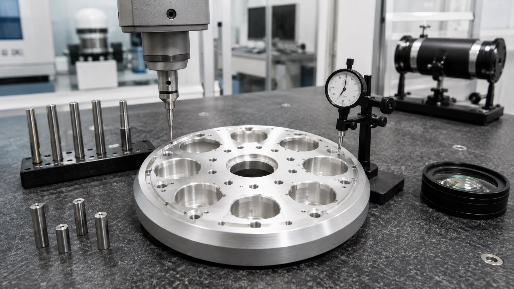
The customer also requested consistent batch documentation. Each lot was linked to material certification, machining revision, inspection results and cleaning status. This record made it easier for the equipment team to compare prototype and pilot batches and to approve the adapter plate for the next assembly stage.
Result
The finished rotor adapter plate met the required concentricity and flatness targets while maintaining a clean machined surface suitable for anodizing. The final geometry reduced unnecessary mass without weakening the hub or mounting regions. The same fixture and inspection plan can be reused for related rotor adapter plates, making the process suitable for small batches, engineering changes and controlled production runs.
Conclusion
This case shows how CNC machining supports medical centrifuge component manufacturing when geometry, balance and documentation must be controlled together. By combining 7075-T6 aluminum, staged machining, dedicated fixturing, CMM inspection and clean packaging, the rotor adapter plate can move from prototype to production with fewer assembly surprises.
FAQ
What was the product in this case study?
The project focused on a 7075-T6 aluminum rotor adapter plate used in a medical laboratory centrifuge assembly.
Which features required the most control?
The central bore, radial pockets, mounting counterbores, dowel holes, flat mounting face and circular runout were the most critical features.
Why was a staged machining process used?
Staged roughing, semi-finishing and final datum machining reduced stress movement and helped maintain flatness and concentricity.
How was the part inspected?
The lot was checked with CMM measurement, gauge pins, height inspection, runout verification and visual edge inspection after deburring.
Can the same design be customized for other tube layouts?
Yes. The pocket pattern, center bore, mounting holes and surface treatment can be adjusted for different tube formats or rotor interfaces.
How were finished parts prepared for shipment?
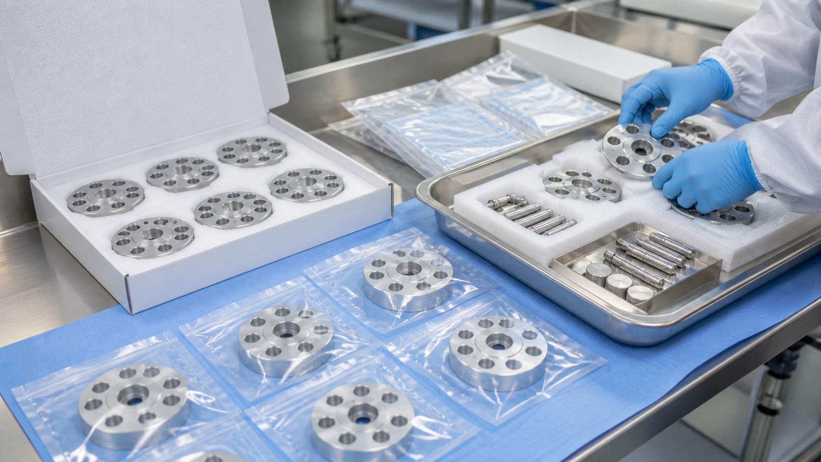
Parts were cleaned, separated with foam, individually protected where needed and packed with batch identification and inspection status.
Contact: tanghangyun@oemach.com