
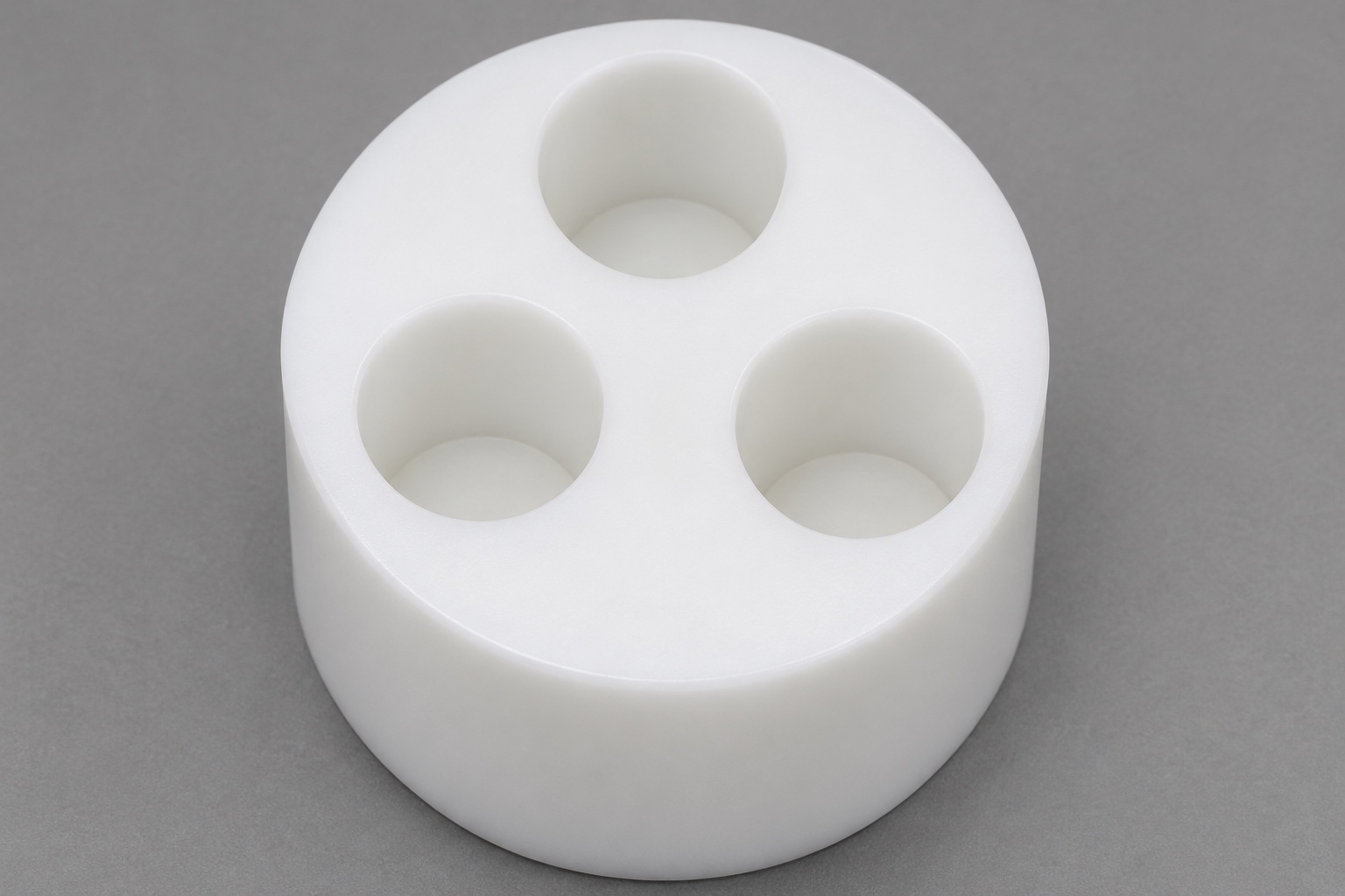
Representative scope and evidence boundary
This case proposes a natural unfilled POM-C parking puck for an inert diagnostic pipette fixture. It is a representative manufacturing example, not a documented customer delivery or qualified laboratory workflow. No achieved tolerance, certification, volume-accuracy result, contamination-control result or clinical suitability is claimed. The purpose is to structure a machining inquiry and its inspection plan. Actual pipette contacts and application requirements would be defined by the responsible fixture project. The accompanying images are not certificates, production records or proof that a real customer's parts passed dimensional, cleaning or functional qualification.

Proposed solid puck geometry
The component is a short round cylinder with flat top and bottom and exactly three equal plain blind bores arranged in a triangular pattern from the top. All three cavities have defined flat floors and stop before the bottom face. There is no fourth central hole, through-hole, thread, flange, groove or inserted hardware. Small specified edge treatments would be controlled by the drawing. A component with drill-point-shaped floors or penetrated bottoms would be a different geometry. The model and specification would establish actual dimensions and acceptance criteria rather than allowing the supplier to infer them from the appearance of a familiar parking stand.
Define the inert reference interface
The drawing owner would identify the allowed contact surfaces, entry clearance and whether an approved inert reference may touch the cavity floor. The puck's location and retention within the fixture would also need definition. A reference that enters a cavity would not establish all diameter, depth or positional requirements. Any optional placement observation would identify revisions and conditions and remain separate from dimensional acceptance. It would not qualify liquid delivery, pipette calibration, cleaning efficacy or contamination control. Those responsibilities belong to the real laboratory workflow and require evidence designed for that application rather than an assumption based on the puck's shape.
Resolve depth, floor shape and remaining material
A real RFQ would define the depth reference plane, usable cylindrical length, flat floor region and permitted bottom transition. It would relate bore depth to external thickness and any required remaining material. Tool travel or the deepest point of an unapproved drill end would not automatically become the accepted depth. If the proposed tooling could not create the required floor, the issue would be clarified before manufacture. Accidental breakthrough would not be accepted as an equivalent design. The case assigns no numerical floor or strength value; those requirements would come from the controlled drawing and responsible engineering review.
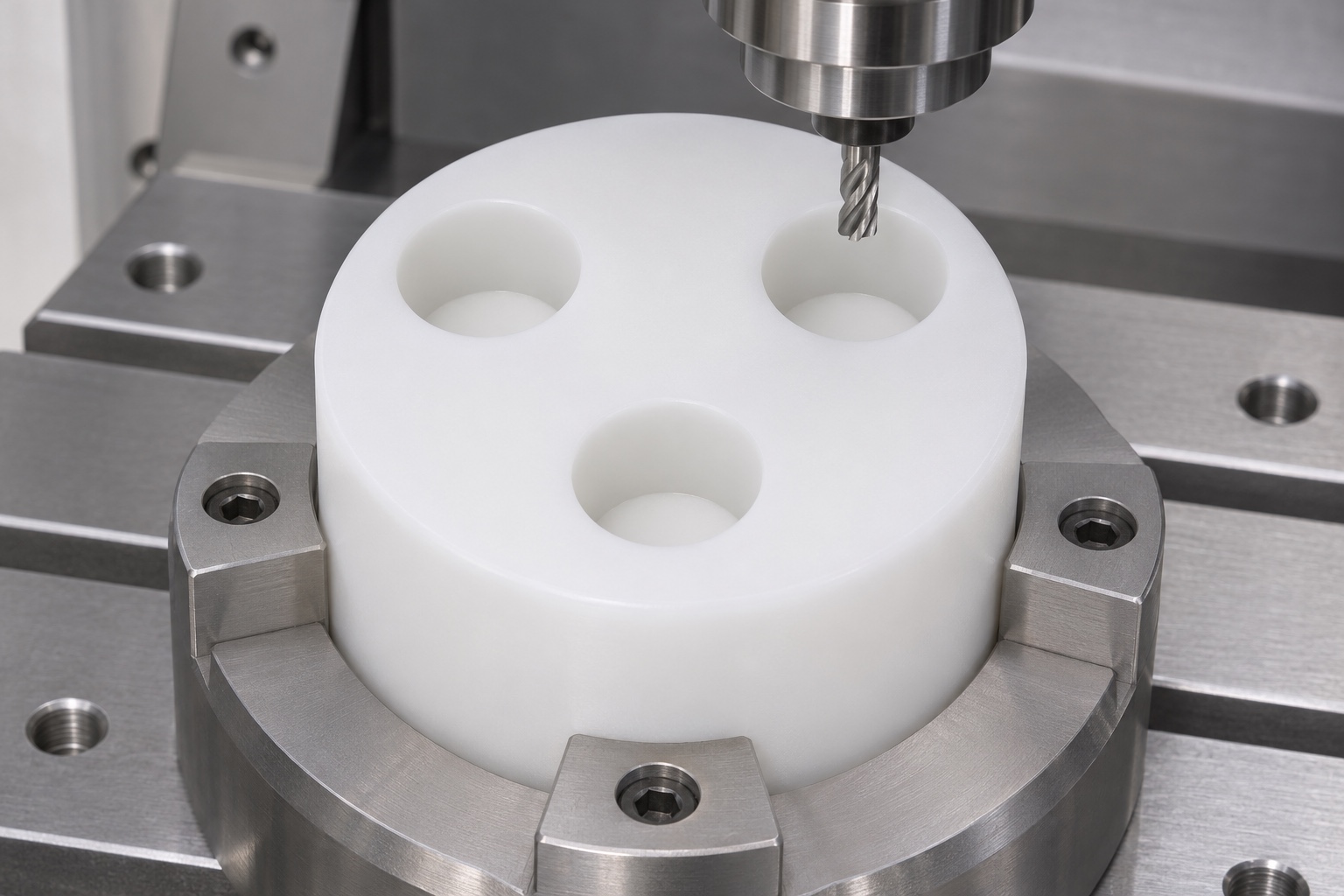
Specify the actual POM-C stock
An actual order would identify the required acetal copolymer grade, stock form and supporting source documentation. Natural white color would not establish material identity. POM-H or another material would not be substituted simply because it looks similar or shares an acetal label. Records would remain linked through circular preparation, bore machining and approved subsequent steps. This example supplies no actual certificate or chemical-exposure result. Material documentation would identify what was supplied within its scope, while finished dimensions, cleaning condition and application suitability would still need their own requirements and evidence.
Propose a coordinated turning and bore-machining route
A candidate process would prepare the cylinder and faces, transfer the intended references and machine the three blind cavities with suitable support. The actual sequence would depend on dimensions, grade, tooling access and tolerances. It would review material remaining around and below each bore as well as the effect of the selected holding arrangement. The flat-floor operation and any finishing allowance would be explicit rather than assumed. No cutting parameters, cycle time or achieved accuracy are invented. This is a proposed route to evaluate, not a claim that a qualified production process has already delivered accepted parking pucks.
Define the final measurement condition
The manufacturing plan would identify support, restraint and any conditioning relevant to the completed polymer part. Dimensions recorded under strong clamping would not silently represent the supplied state. An intermediate circular blank would not be treated as evidence for the final three-cavity geometry. If development observations justified a stabilization step or changed sequence, those findings would be documented and verified. The case reports no measured distortion or improvement. Its aim is to align the process and inspection with the intended condition rather than predict a universal behavior for every POM-C grade or use an unexplained waiting interval as a guarantee.
Preserve entries and flat floors during finishing
Deburring would remove unwanted material without changing bore size, usable depth, entry contact or floor geometry. Local bottom transitions would remain as specified instead of being broadly polished until all cavities looked alike. Any proposed taper, relief or different bottom shape would require approval and updated inspection requirements. Tools and handling would match the outgoing condition actually requested. A smooth white surface would not establish cleanliness, biological suitability or compatibility with a particular reagent or cleaning exposure. Those claims would stay outside this machining proposal unless separately specified and supported by appropriate evidence.
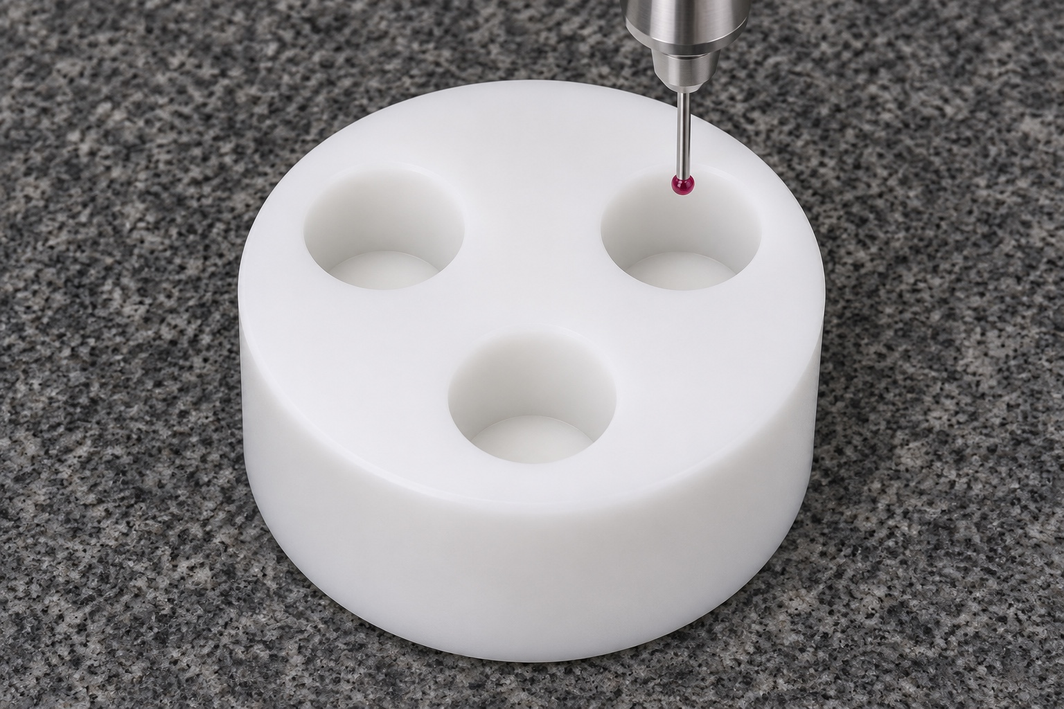
Plan separate checks for depth, size and layout
A proposed inspection plan would identify the top reference plane, depth contact location and access to the specified flat floor region. It would distinguish cavity depth from bore size, layout and remaining material. A coordinate approach would require suitable alignment and measurement capability, not merely a visible probe. Any calculated floor result would identify external thickness, cavity observations and relevant relationships. Since no verified delivery data accompanies this example, it claims no numerical result. Actual release would require observations from the completed parts after operations capable of affecting the specified characteristics.
Organize traceable first-article evidence
The record would connect drawing revision, material identity, approved clarifications, final process state and results by feature. It would separate nominal dimensions, measured observations and calculations. If access or uncertainty prevented a method from evaluating a requirement, the limitation would be resolved before acceptance. Deviations would follow an authorized disposition process rather than an informal statement that three references fit. A real first-article package could support repeat purchasing decisions; this representative route and its images could not substitute for that package or be presented as a completed manufacturing achievement.
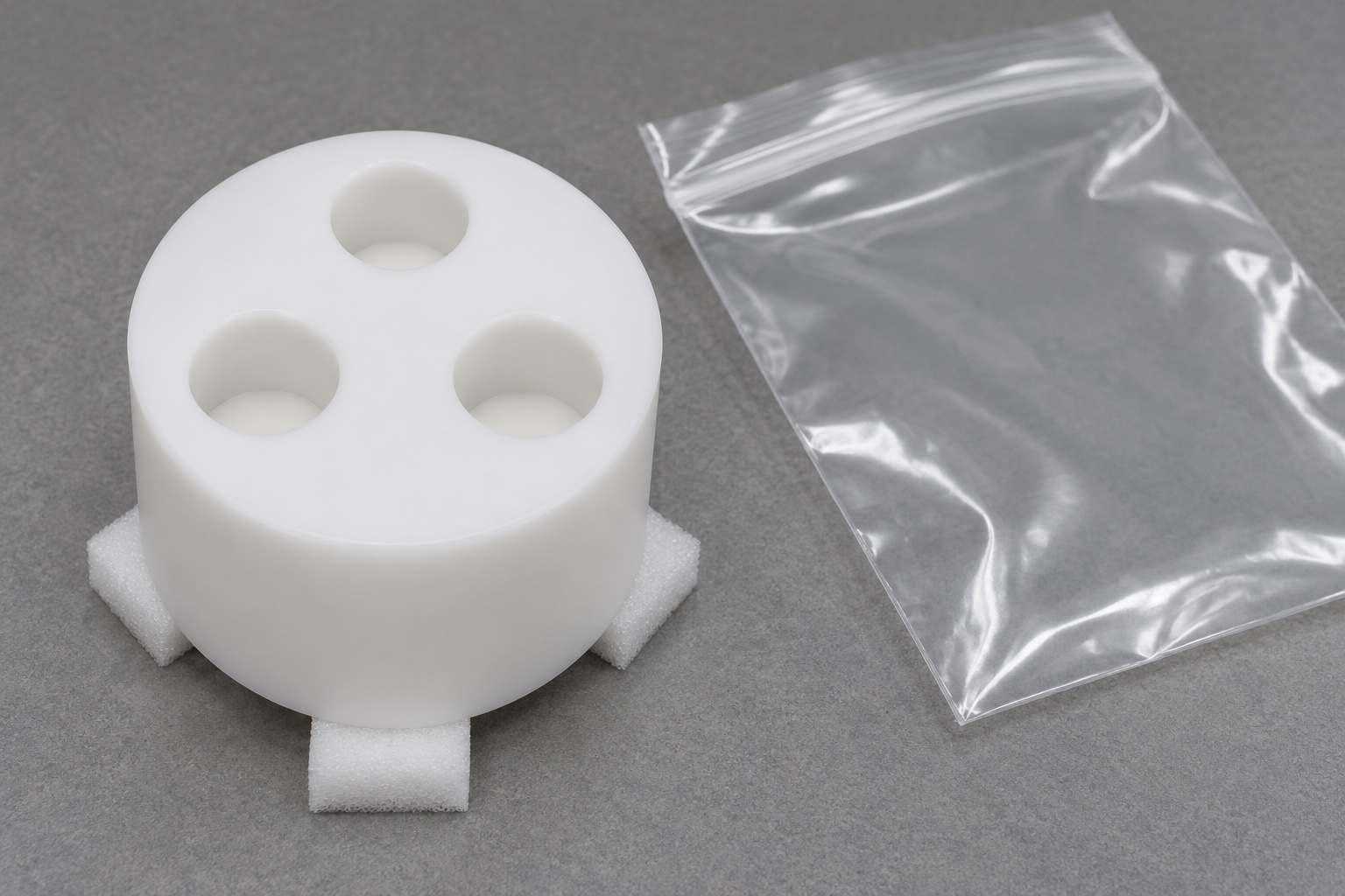
Protect blind cavities and identification in packaging
The outgoing plan would address retained loose material, entry protection and identification of material and revision. The puck would be separated from loose hardware that could damage a floor or bore wall. Specific residue or cleaning requirements would need an agreed process and verification. Protective pads and an ordinary pouch would not constitute sterile packaging, validated cleaning or qualified transport. No shipment outcome is asserted. The supplier's documented machining and handling scope would remain explicit, while any additional application qualification would be assigned separately by the responsible diagnostic fixture project.
Approve a bounded scope before production
Before a genuine small-batch order, the parties would approve grade, cylinder references, bore size, layout, depth definition, flat floors, remaining material and edge treatment. DFM review would resolve access, support, reference transfer and final inspection condition. Actual first-article findings and authorized changes would support later lots. The quotation would describe measurable custom POM-C machining rather than guarantee pipette accuracy or workflow cleanliness. This case provides a practical comparison framework without fictional customers, achieved precision or diagnostic performance that the proposed component manufacturing alone cannot establish.
FAQ
Does this describe a delivered laboratory product?
No. It is a representative machining proposal. It claims no actual delivery, achieved tolerance, certification, calibration result or qualified workflow. An actual order would require its own controlled evidence and release records.
What distinguishes the three bores from drilled through-holes?
They stop before the flat bottom and have specified flat floors. There is material underneath each cavity. Through-holes, extra holes or different floor shapes would change the defined component.
Why not accept the deepest tool point as bore depth?
The drawing may define a flat floor and usable cylindrical region that differ from a tool's deepest point. Specify the reference plane, contact location and transitions so machining and inspection evaluate the same characteristic.
Can three fitting references release the layout?
No. They can support a limited agreed assembly observation but do not establish every bore dimension, depth, spacing or reference relationship. Use suitable feature-specific inspection for the controlled requirements.
Does the material name prove cleaning compatibility?
No. Exact grade, exposure, processing and application requirements matter. Material identity alone does not demonstrate validated cleaning, contamination control, biological suitability or pipette performance.
What supports a repeat small-batch order?
Use approved material and geometry, real final inspection results, authorized changes and agreed cleaning and packaging requirements. This proposed route and its images are not completed production or application qualification.

tanghangyun@oemach.com