
Representative scope and evidence boundary
This representative CNC turning case considers a solid 316L conical locator for an inert surgical instrument inspection fixture. It is a manufacturing-planning example, not an identified customer delivery or a report of achieved production results. No certification, measured tolerance, positioning repeatability, holding force or clinical performance is claimed. The purpose is to organize questions that a drawing owner and machining supplier would resolve before accepting a real order. Component conformity remains separate from the validation of the full fixture and the instruments evaluated with it. Photographs accompanying the example are not material certificates, inspection records or evidence that a customer project was completed.

Proposed part geometry and excluded features
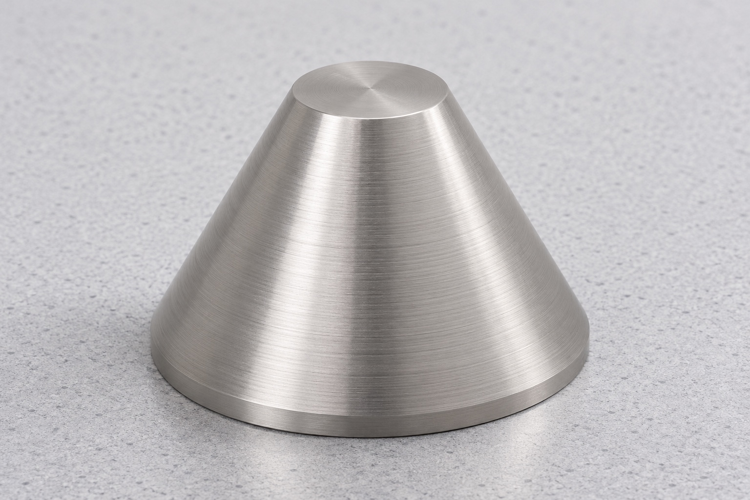
The component is a single truncated circular cone with a broad flat bottom, smaller flat top and straight tapered side. It is solid throughout and has no axial bore, thread, shaft extension, projecting flange or attached fastener. Small permitted edge treatments would be identified outside the usable taper region. The drawing, rather than a photograph, would establish dimensions and acceptance criteria. This envelope should not be mistaken for a threaded cone adapter or a locating pin with an added shank. Any mounting or retention arrangement belongs to the separately defined fixture interface and cannot be invented from the component's simple exterior.
Define the mating contact before assigning tolerances
The fixture designer would identify which portion of the taper contacts the mating reference and which surface establishes axial seating. The bottom face might locate against a support, but its role would need explicit confirmation. Clearance at the smaller top and broad edge would also be reviewed. A contact region cannot be defined reliably by saying that the cone should fit. The review would distinguish dimensional requirements for the locator from force, stability or repeatability requirements for the assembly. An optional inert placement check would have a stated scope and reference revision rather than acting as an undocumented substitute for drawing acceptance.
Resolve the taper convention in the RFQ
A real request would state whether the angular value is a half-angle or included angle and define the controlled axial length. Diameter values would apply at named planes or distances from the specified reference. The review would reconcile tolerances on angle, length and diameters instead of assuming they are independent. Edge breaks would be separated from the working region. A nominal geometric relationship may help explain the intended cone, but it does not establish final surface form. Any mismatch between model and drawing would be returned for clarification and recorded under the correct revision before preparing a production route.
Preserve material identification through preparation
Identified 316L stock would be associated with the requested source documentation. Blank preparation would leave material for the taper, end faces and necessary temporary holding allowance without silently adding a feature to the finished design. The material record would follow the part through machining and approved treatments. If marking a contact surface were prohibited, a controlled container and manufacturing record would preserve identification. This case supplies no actual material certificate or passivation result. It explains what a real order would need, while avoiding the assumption that stainless appearance proves alloy, surface treatment, cleaning quality or suitability for a particular medical exposure.
Propose a turning sequence around setup transfer
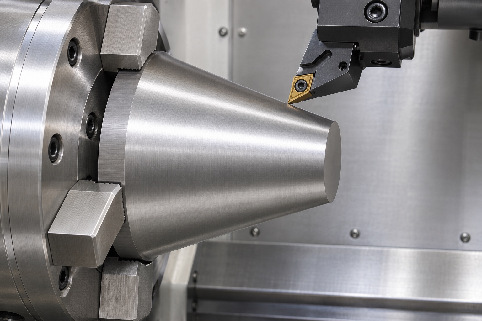
The candidate process would coordinate end-face preparation and external taper turning with the available workholding and access. If completing the bottom required another setup, the plan would describe how the intended geometric relationship is recovered. A chuck contact surface would not automatically become the drawing reference. Temporary holding allowance would be removed as required without damaging the working band. Tooling and parameters would be selected for the actual geometry and material. The example does not assert a qualified cycle, a production time or an achieved tolerance. It instead asks how the chosen sequence preserves the relationships that the final inspection must evaluate.
Control transitions and final surface handling
The drawing would identify the permitted treatment of the small top edge and broad bottom edge, including any excluded measurement zones. Deburring would remove unintended material without creating a broad blend in the contact region. If polishing were proposed, its purpose and effect on the taper would be reviewed rather than accepted as an automatic improvement. Surface-texture requirements would be kept distinct from cosmetic appearance. Tools, supports and handling would protect the finished side from isolated raised marks. Changes to reliefs or usable contact length would require approval and corresponding inspection updates, not an informal adjustment made to simplify finishing.
Select inspection methods for the actual characteristics
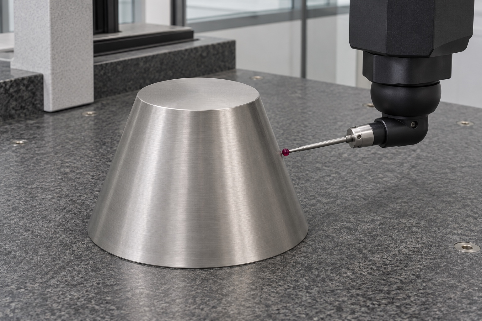
A proposed inspection plan would evaluate defined diameter planes, angular convention, length, relevant face relationship and surface requirements using suitable methods. A fitted profile or distributed coordinate measurements might be appropriate, subject to capability and access. The plan would identify the reference condition and exclusion of edge transitions. A diameter reading alone would not release the taper, and a visually plausible contact mark would not replace surface-form evidence. This case reports no numerical inspection result because no real delivery data supports one. An actual first-article report would contain observations from the completed parts, with any derived values identified clearly.
Build a traceable first-article record
The proposed record would link drawing revision, approved clarifications, stock identification, final processing condition and feature-level results. It would distinguish nominal values, measured observations and calculated characteristics. Measurements made before a later operation could support process control but would not silently represent the final surface after that operation. Where access or uncertainty limits a method, the limitation would be resolved before acceptance. Nonconformities would follow the buyer's authorized disposition process. A real first-article package would therefore document what was actually evaluated, not merely present a machine photograph or repeat this representative route as if it were an achieved manufacturing result.
Treat fixture placement as supplementary information
If agreed, a controlled inert fixture reference could be used to observe obvious interference or the intended seating region. The record would state both revisions and the observation conditions. It would not establish contact force, positioning repeatability, wear life or accuracy of a surgical instrument inspection system. An unfavorable observation could involve either mating component or its support arrangement and would require investigation. A favorable visual fit would not override a failed dimensional requirement. This case does not claim any completed assembly trial; it separates that possible activity from the manufacturing and inspection evidence needed for the locator itself.
Define protective packaging without extending its claims
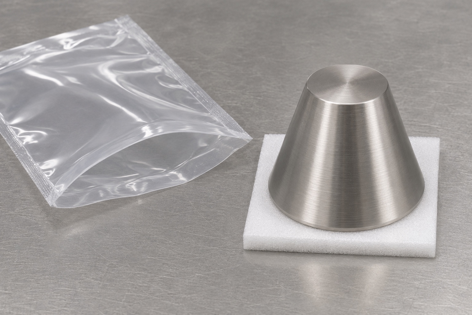
The proposed outgoing condition would address residues, contact-surface protection and identification. Separate locators would not be allowed to rub tapered bands or edges against one another. The packaging record would preserve material and revision links without marking restricted surfaces. Any specific residue limit would require an agreed cleaning and verification method. A protective support and ordinary pouch would not demonstrate sterile packaging, validated cleaning or qualified shipping performance. No actual shipment is asserted. The supply description would remain limited to what the supplier can document, with any additional cleaning, transport or application qualification stated as a separate requirement.
Establish a bounded release path for a real order
Before production, the parties would approve geometry, taper convention, axial references, material, surface state, inspection and packaging. DFM review would address workholding, transfer, contact protection and measurement access. Actual first-article evidence and authorized changes would then support any repeat small-batch order. The supplier would quote a defined 316L CNC turning scope rather than guarantee a fixture result based on a simple cone shape. This representative case gives a practical structure for that discussion without inventing customer achievements, certifications or medical performance that component manufacturing alone cannot establish.
FAQ
Is this a documented customer delivery?
No. It is a representative manufacturing example. It claims no actual customer, delivery quantity, achieved tolerance, certification, positioning result or clinical use. A real order would need its own controlled evidence and release records.
Does the proposed locator have a bore or shaft?
No. It is a solid truncated cone with flat circular ends and one straight tapered side. No bore, thread, shaft extension, projecting flange or assembled fastener is included in this proposed geometry.
What taper information must be clarified before quoting?
Define the angular convention, axial reference, controlled length, diameter evaluation planes and usable contact region. Reconcile related tolerances and identify how edge transitions are treated before the supplier selects a process.
Can a photograph replace the first-article report?
No. A report requires traceable part observations, suitable methods and evaluation against controlled requirements. A photograph does not establish material identity, angle, surface form or any achieved dimensional result.
Would a seating observation prove fixture accuracy?
No. It would support only the agreed observation with a controlled reference. Fixture accuracy, force, repeatability and life need separately designed evaluations of the relevant assembly and operating conditions.
What supports a repeat small-batch purchase?
Use approved drawings, material records, final inspection evidence, authorized changes and agreed packaging requirements. Do not treat this proposed process or its images as completed production qualification or actual delivery results.

tanghangyun@oemach.com