
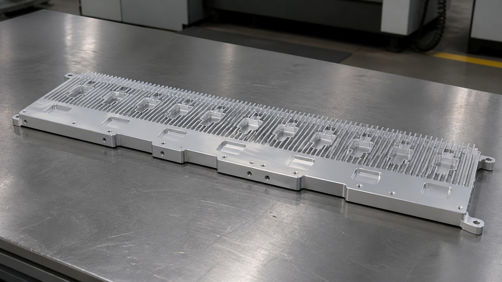
Summary: This is a sanitized machining review for an AL 6063-T6 plate-style heat sink used in an automation fixture context. Visible drawing data includes dense cooling fins, repeated pockets, counterbore slot features, 16-M2.5 threads, flatness control, fine sandblasting, and bright silver anodizing. OEMACH reviews such parts by confirming datums, assembly relationships, machining sequence, surface finishing, and packing protection before small-batch production.
Visible drawing data
The drawing indicates an aluminum plate heat sink made from AL 6063-T6. Visible dimensions include an overall width around 421 mm, overall height around 193 mm, main length around 395.75 mm, and thickness around 24.80 mm. Local values include 119.52 mm, 103.52 mm, 59.40 mm, 43.40 mm, 17.30 mm, 10.25 mm, and 4.80 mm. The drawing also shows 16-M2.5 threads, dense fins, rounded pockets, counterbore and slot areas, flatness 0.3 mm, fine sandblasting, bright silver anodizing, and appearance requirements against scratches, whitening, and stains. [Source: Customer-provided visible engineering drawing annotations]
Application and machining risks
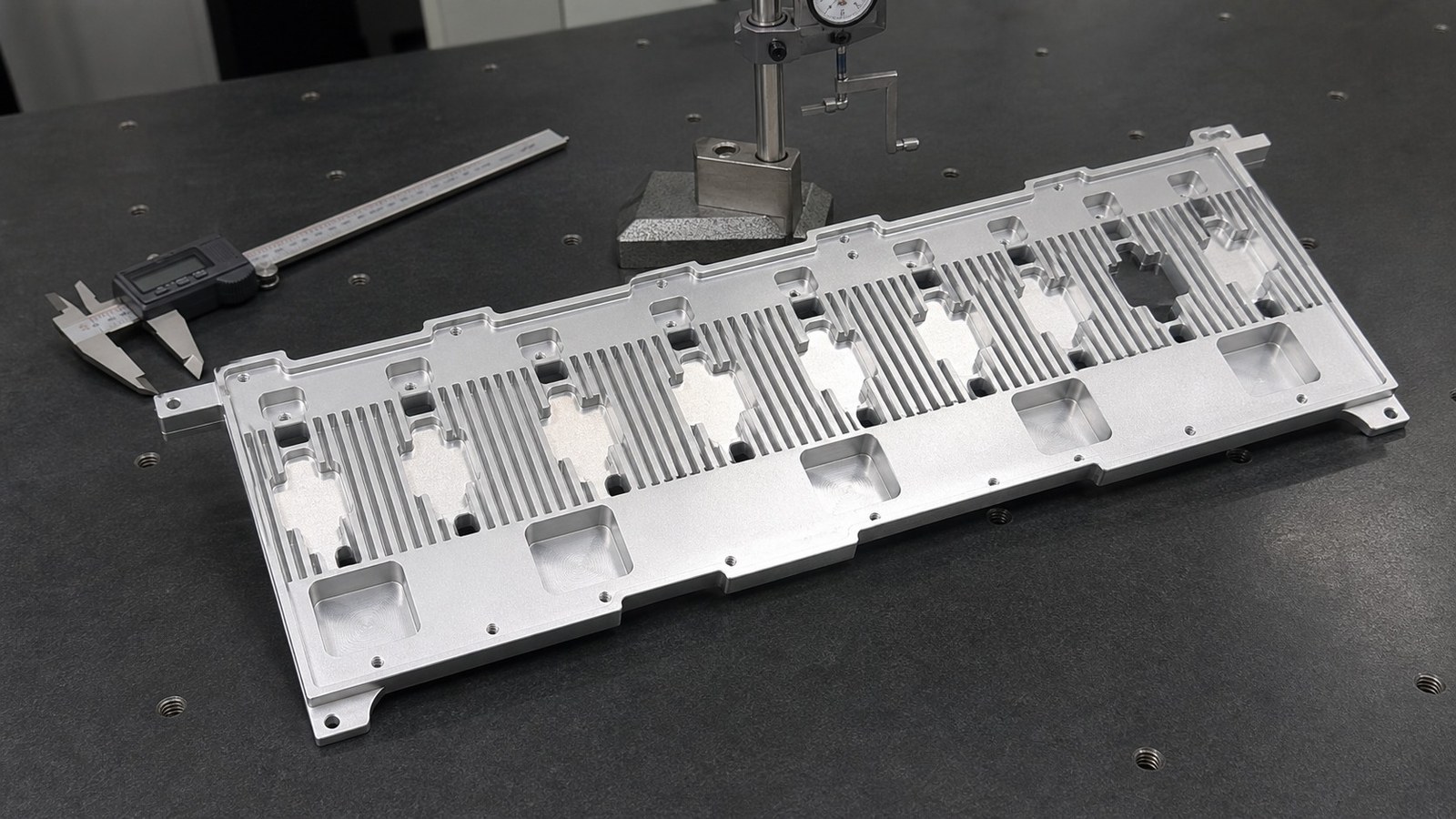
Engineer Wu treated the part as both a heat dissipation component and a mounting carrier in an automation fixture. The large plate provides a stable mounting base, the dense fins increase heat exchange area, and the holes, slots, and threaded features connect the fixture body or adjacent modules. If the counterbore depth, slot position, or datum relationship changes, assembly may show screw head interference, mismatched mating parts, or uneven plate contact.
The main risk is the combination of a large plate body and dense thin fins. Clamp force must avoid the fin area, and support should be placed on rigid regions. A second risk is datum transfer between the plate face, pockets, threaded holes, and slot positions. A third risk is surface treatment: fine sandblasting and bright anodizing may reveal earlier scratches or handling marks.
Geometric relationships should be interpreted using the controlled drawing and applicable GPS framework. [Source: ISO 1101:2017] General linear tolerances should not replace specifically marked tolerances. [Source: ISO 2768-1:1989]
Process approach
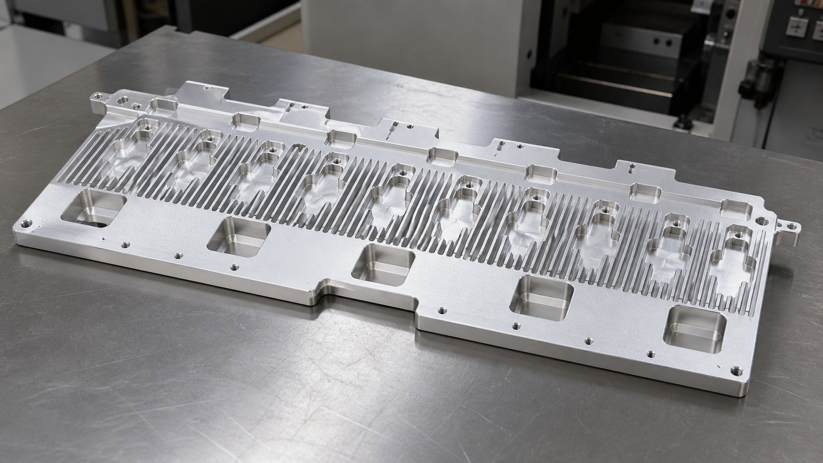
Engineer Wu would normally start with drawing review and datum planning, then confirm raw material and support strategy. Roughing, local feature machining, and final finishing should keep a stable reference path. Related holes, slots, and counterbores should be completed under controlled setup conditions where possible, and burr removal must not widen the functional boundaries.
For the 16-M2.5 threads, bottom hole condition, tapping rhythm, chip removal, and thread entrance burrs need attention. The drawing calls for thread checking with go/no-go gauges, so thread review should be linked to the batch record. [Source: Customer-provided visible engineering drawing annotations]
Flatness 0.3 mm should be reviewed after releasing the part from the fixture, because a large aluminum plate may behave differently under clamping force and in a free state. Symmetric stock removal, staged machining, reasonable support, and post-release review help reduce uncertainty.
Surface treatment and packing
Fine sandblasting can create a uniform surface texture, but pre-existing scratches, local polishing marks, cleaning differences, or hard-contact handling may become visible after bright silver anodizing. Surface texture requirements should be evaluated according to technical documents rather than a single viewing angle. [Source: ISO 21920-1:2021]
During packing, the fins should not be used as the main load-bearing area. The part should be placed in a fixed direction with soft support on rigid regions. Individual isolation helps prevent friction marks on anodized surfaces during transport.
Supplier selection notes
For this type of plate heat sink, supplier selection should not focus only on machine travel. The buyer should also check whether the supplier can understand fixture assembly relationships, maintain datum consistency for counterbores, slots, and threads, review the plate after unclamping, coordinate surface treatment, and protect the anodized surface during delivery.
FAQ
Q1: Why review flatness after unclamping?
A large plate can change shape when clamping force is released. Reviewing flatness in a stable free state is closer to the assembly condition. [Source: ISO 1101:2017]
Q2: Are counterbores checked only by diameter and depth?
No. Their relationship to the datum, screw head position, bottom surface, and adjacent slot features also affects assembly.
Q3: Why are M2.5 threads sensitive?
Small threads are affected by bottom hole condition, chip removal, tool wear, surface treatment, and burrs at the thread entrance.
Q4: What should be provided for quotation?
A controlled drawing, expected quantity, assembly relationship, surface treatment requirement, packing condition, and any mating-part information should be shared before process confirmation.
Escanee para contactarnos
Contacto: Allen
Correo electronico: shiziqiu@oemach.com
My whatsapp code